

 EnglishEN
 ItalianoIT
 DeutschDE
 EspañolES
 PortuguêsPT
 РусскийRU
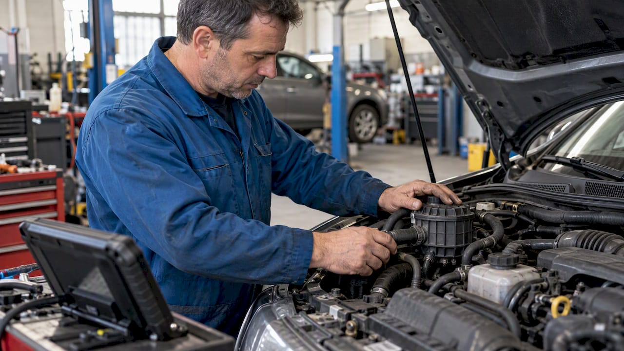
Secondary air off describes a change to secondary air injection control, not a diagnosis of the original fault. Pump noise, a stored code or an extinguished warning lamp cannot establish whether the system delivers the required air. Start by identifying the hardware and the conditions under which the ECU commands and monitors it.
Secondary air off: distinguish operation from monitoring
Secondary air supplies oxygen to the exhaust to support oxidation of hydrocarbons and carbon monoxide during relevant operating conditions, commonly after a cold start. System layouts differ: an electric pump, pneumatic valve and particular relay arrangement should not be assumed on every vehicle.
Control and monitoring may use temperature, time, operating state and sensor feedback. Pump shutdown is not universally synchronized with oxygen-sensor warm-up or closed-loop entry. Confirm the strategy for the actual application.
HELLA’s guide provides an overview of components and diagnostic methods. Use its general principles alongside vehicle-specific electrical diagrams and test information, rather than copying an example sequence to every system.
Capture the fault and check what the code means
Save the complete DTC, status and freeze-frame information before clearing anything. A flow fault, an electrical-circuit fault and a valve-position fault are different findings. Confirm manufacturer-specific descriptions and bank identification.
An audible pump may rotate without delivering sufficient air through the complete system. A silent pump may not have been commanded under the current conditions. Neither observation alone proves a good pump or a failed one.
Inspect the relevant hoses, connectors and exhaust-side connections. Moisture, heat damage, a restriction or reverse flow can contribute to failure. If a replacement pump fails again, examine the surrounding system rather than assuming the replacement part was defective.
Test electrical supply under the appropriate load
Use supported actuator tests where available and confirm the command is accepted. Check supply and ground behavior with a method appropriate to the circuit. An unloaded voltage measurement can look normal despite a connection that fails under load.
Voltage present at an unplugged connector does not by itself prove that the pump is faulty. Ground continuity alone also does not establish adequate current-carrying performance. Use the wiring diagram and specified checks to isolate the fault.
Do not assume every pump can be powered directly or every controller uses a simple relay. Follow the applicable test method and duty limits.
Test valves and airflow according to their design
A valve can combine isolation and reverse-flow prevention, but designs vary. Vacuum testing applies to pneumatic components with the specified test conditions; it is not a universal test for electrically operated valves.
Check the full air path rather than only pump rotation. A blocked passage, disconnected hose or valve that fails to open can prevent delivery. Conversely, failed isolation may expose components to exhaust gas or condensate.
Replacement parts must perform the required functions. A generic check valve is not automatically equivalent to an original combination valve. Repair the diagnosed defect and assess any associated damage.
Separate repair, software changes and emissions evidence
Disabling a command, suppressing a DTC and changing monitor behavior are distinct software actions. None repairs a damaged hose, restores missing airflow or demonstrates that cold-start emissions remain unchanged.
U.S. EPA guidance addresses tampering with emissions-related elements and aftermarket defeat devices. A reversible modification or a race-use label does not by itself establish compliance. Inspection preparation should not be confused with proof that the underlying configuration is lawful.
For additional context, the emissions evidence guide distinguishes diagnostic observations from testing and approval documentation. A file service should not be described as providing certification unless that is actually documented.
Verify the repaired system under the required conditions
Repeat the relevant test after repair and record the result. A warm restart may not enable a cold-start monitor. Clearing codes can reset readiness, and the absence of an immediate returning code does not prove that the monitor has completed.
Confirm supported operation, relevant feedback and completion status as specified for the vehicle. Persistent faults require further diagnosis; there is no universal cold-start duration or number of drive cycles that proves success.
For file-service availability and commercial terms, consult the Liste des prix de TuningBot. Checksum correction, review and guarantees must follow the actual order terms rather than assumptions in a diagnostic article.
Questions fréquemment posées
Does pump noise prove the secondary air system works?
No. The pump may run while air delivery is restricted or a valve fails to open. Check the complete path and relevant feedback.
Does voltage at an unplugged pump connector prove the pump is faulty?
No. The supply and ground may fail under load. Test the circuit using the application-specific method.
Does one fault-free restart prove the repair is complete?
No. The required operating conditions and monitor completion must be checked. A warm restart may not exercise the relevant function.