

 EnglishEN
 ItalianoIT
 DeutschDE
 EspañolES
 PortuguêsPT
 РусскийRU
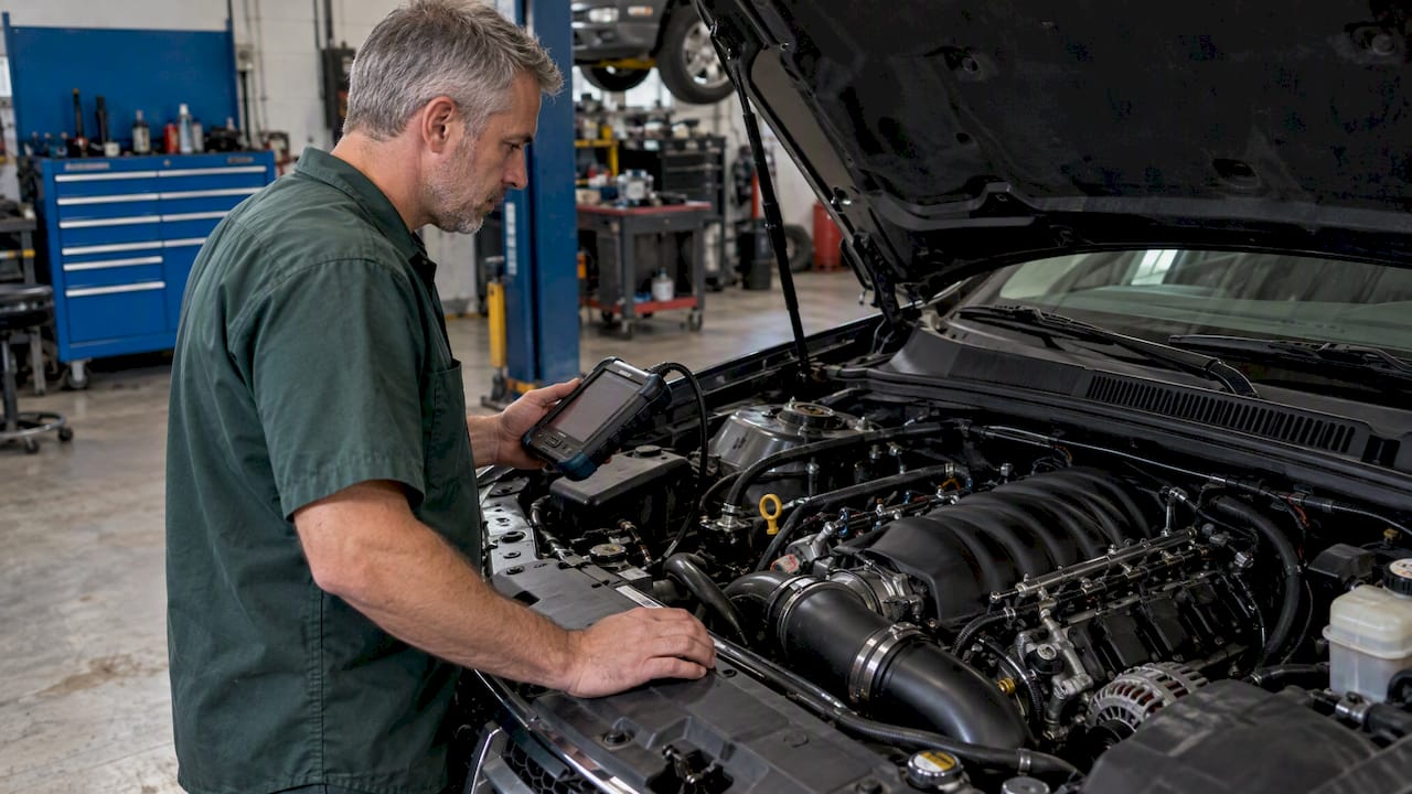
Tuning an LS engine starts with identifying the controller, the installed hardware and the operating conditions the calibration must cover. Fuel delivery, airflow estimation, ignition, idle and torque coordination have to agree with the actual build. There is no single LS tune, universal table-editing sequence or guaranteed power gain: a factory-controlled swap and a standalone-equipped engine can require different tools and validation.
Tuning an LS engine: identify the complete combination
Record the engine variant, displacement, camshaft, compression ratio, injectors, fuel system, intake, exhaust and transmission. Identify the ECU hardware and operating system through diagnostic identification as well as its label. On a swap, the engine, harness and controller may come from different vehicles, so the donor model year alone does not establish compatibility.
- Confirm the actual crank and cam trigger patterns and compatible sensors.
- Match the throttle body, pedal or cable-throttle arrangement, wiring and controller support.
- Record injector part numbers and characterization data for the intended fuel pressure and fuel.
- Identify the transmission controller, required network messages and vehicle functions that must remain operational.
- Check mechanical condition, fuel delivery, ignition, cooling, grounds and fault codes before interpreting calibration logs.
A controller nickname such as “411” is not a complete specification. Nor should an ECU be selected from a broad Gen III/Gen IV label without checking the actual signals, pinout, software and peripherals. An incompatible trigger or throttle arrangement is not repaired by adjusting fueling tables.
During preparation, inspect connectors and wiring for contamination or damage. The guide to cleaning an engine bay provides maintenance context; cleaning does not replace electrical testing, and sensitive components need the vehicle manufacturer’s precautions.
Factory ECU, standalone and remote calibration
A supported factory ECU can retain vehicle integration that a standalone installation must address separately. A standalone offers a different hardware and software environment, but it does not automatically improve a calibration or preserve the original dashboard, body controls and transmission functions.
Le Haltech Nexus Rebel LS quick-start guide describes an LS-specific controller, harness options and supported trigger arrangements. Haltech’s product overview also distinguishes this system from a plug-in replacement for a factory vehicle network. Check the current instructions for the exact ECU, firmware and harness before selecting it.
Remote calibration is a way of performing the calibration work, not a third controller architecture. Whether the file is edited locally or remotely, the person operating the vehicle must supply accurate build information, reliable measurements and controlled tests. A file alone cannot diagnose a fuel-pressure fault or demonstrate safe operation under every load.
Separate airflow errors from fuel-system errors
Depending on the operating system and active mode, cylinder air charge may be derived from the MAF, a speed-density model, or a strategy using both. Speed density is a calculation using pressure, temperature, engine speed and an airflow model; it is not a type of intake sensor.
Start with correct injector characterization and a verified fuel supply. Flow data, voltage-dependent offset and short-pulse behavior must match the injector and the controller’s definitions where those parameters are used. Changing the airflow model to hide incorrect injector data can produce acceptable readings in one area and errors elsewhere.
HP Tuners’ virtual VE documentation explains that some GM strategies use coefficients rather than a directly stored conventional VE table. Its workflow also emphasizes accurate injector data and restoring MAF operation after a temporary isolation procedure. Apply the method appropriate to the actual operating system; do not copy diagnostic-disable settings from another ECU.
Compare commanded and measured lambda in known operating modes. Fuel trims are useful only when their enabling conditions and learned corrections are understood. A wideband installation must have suitable sensor placement, correct logger scaling and no relevant exhaust leaks. Misfire can leave excess oxygen in the exhaust and produce an apparent lean reading; adding fuel is not automatically the remedy.
Notre fuel map tuning guide explains the relationship between fueling, airflow and torque calculations.
Build a useful baseline and change record
Archive the existing calibration and controller identification using the supported read method. Label the file as the current read, rather than assuming a previously modified vehicle still contains factory software. Record which memory regions the tool actually reads: a calibration file is not necessarily a complete backup or a guaranteed recovery route.
If the installed hardware makes the current calibration unsuitable, establish a compatible starting configuration before running the engine. A stock file should not be used for a loaded baseline merely because it is stock.
| Log group | Objectif |
|---|---|
| RPM, throttle, MAP, airflow and operating mode | Identify where the engine is operating and which strategy is active. |
| Commanded lambda, measured lambda and fuel corrections | Compare fuel control with combustion feedback in valid conditions. |
| Fuel pressure and injector operation, where available | Separate delivery limits from calibration errors. |
| Spark, knock response and temperatures | Understand timing corrections and thermal conditions. |
| Torque requests, interventions, gear and transmission data | Explain coordination between engine and drivetrain controls. |
Channel availability, meaning and sample rate depend on the ECU and logger. Some values are modeled or commanded rather than measured. Keep a change log and test a defined hypothesis with each revision. Closely related parameters may need coordinated edits; the aim is traceability, not an inflexible one-cell-per-flash rule.
Validate idle, spark and drivetrain behavior
Idle calibration includes starting, warm-up, return to idle and accessory loads. A larger camshaft may alter airflow and stability, but a higher idle target alone does not resolve incorrect injector data or a vacuum leak. Test transitions as well as steady operation.
Refine ignition with reliable combustion and torque evidence. Absence of logged knock does not prove that additional advance is beneficial or safe. Knock detection, fuel quality, charge temperature and repeatability all affect interpretation. See the spark advance tuning guide for the distinction between best-torque timing and knock limits.
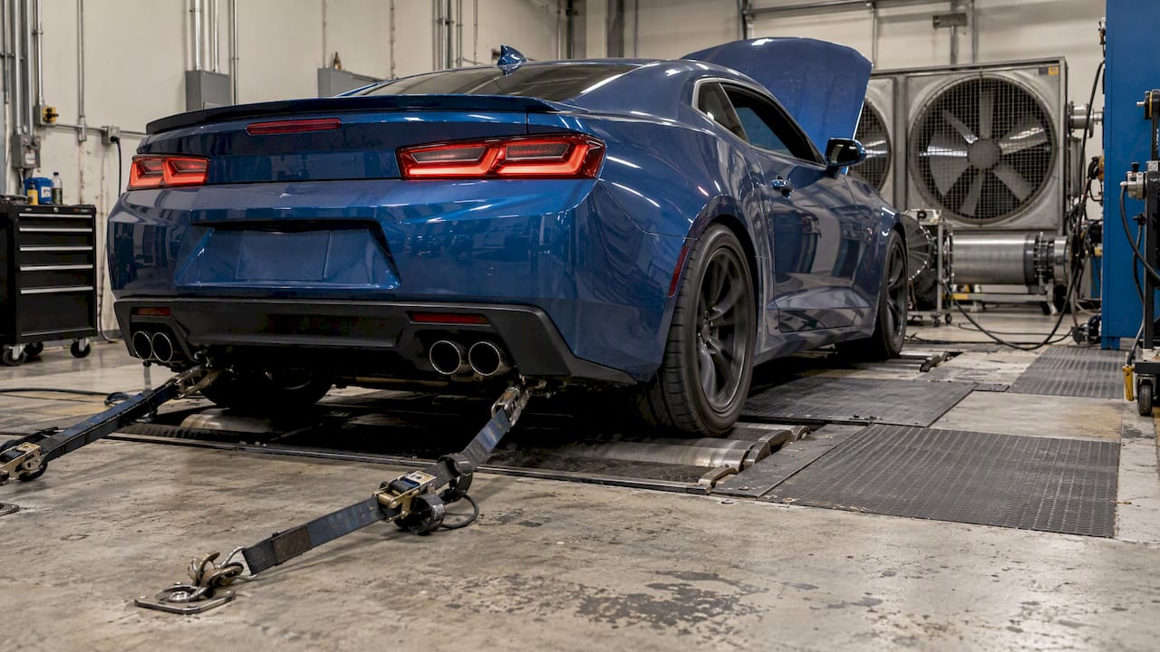
A suitable dyno provides controlled loading, but the test gear, ramp rate and load limits depend on the transmission, tires, cooling and equipment. There is no universal requirement to use a particular gear or ratio. Full-load testing needs a suitable controlled facility and competent operation; public traffic is not a calibration environment.
Where an automatic transmission is involved, evaluate torque reporting and interventions with shift behavior. Do not remove torque management or raise pressure as a default shortcut. Final checks should include temperatures, fault codes, starts, drivability and the vehicle functions affected by the work. Retain required emissions and diagnostic functions and confirm the requirements applicable to the vehicle’s use.
Questions fréquemment posées
Can I use the same tune on every LS engine?
No. The calibration must match the controller software, engine hardware, injectors, fuel, sensors and drivetrain. A shared engine-family name does not establish compatibility.
Does an LS engine need speed-density tuning?
Not automatically. The appropriate airflow strategy depends on the ECU, operating system and installation. A working MAF system should not be removed solely because another build uses speed density.
Is a saved calibration a complete ECU backup?
Not necessarily. The read method determines which memory regions are available. Confirm what the tool saves and which recovery operations it supports for that controller.
Does no knock retard mean the ignition timing is safe?
No. Knock detection and logged channels have limitations. Timing decisions also require reliable torque evidence, correct fueling and evaluation of temperatures and fuel quality.
Does a dyno guarantee a good tune?
No. A suitable dyno helps provide controlled loading and repeatable measurements, but the calibration still needs competent interpretation and validation across the relevant operating conditions.
Pour en savoir plus
The original articles below provide additional perspectives on LS builds and calibration. Their examples are not universal settings, compatibility lists or performance guarantees.
- GM Gen III LS PCM/ECM: Tuning Software and Equipment, LS Engine DIY
- LS Engine Controllers, Chevy Hardcore
- How to Tune an LS With Your Phone, TuneBench
- Flying Blind Part II: What To Data Log When Tuning A Vehicle, LSX Magazine
- Dyno Vs Road Tuning Vs E-Tune, High Performance Academy
- Episode 117: Got an LS? Here’s How to Get the Most Out of Tuning It, High Performance Academy