
 EnglishEN
 ItalianoIT
 DeutschDE
 EspañolES
 PortuguêsPT
 РусскийRU

MAP sensor scaling is the conversion the ECU uses to turn the sensor’s analog voltage into an absolute pressure value. It is a linear relationship defined by two numbers, a slope (the pressure change per volt) and an offset (the pressure at zero volts), or by two voltage and pressure reference points from which the ECU derives them. When a sensor with a different pressure range is fitted, or a file is adapted for different hardware, those values must match the sensor’s transfer function. If they do not, every load, boost and fueling calculation that depends on manifold pressure inherits the error. This article covers the math, the parameters you will meet in different ECU families, a pre-write file check and a validation routine with live data.
TL;DR
- Scaling is a two-point linear conversion: slope = pressure range ÷ voltage range, offset = minimum pressure minus (minimum voltage × slope). Work in one unit system throughout.
- Take the sensor’s transfer function from its datasheet, not from the connector or a forum post. Supply voltage, pressure range and the voltage limits at both ends all matter.
- Before writing a file, check units, axis sizes, conversion factors and duplicate or shadow maps, and confirm the plausibility limits still fit the new voltage range.
- Validate with key-on engine-off readings against ambient pressure, then log under load and compare commanded and actual boost.
- Scaling errors often set no DTC, so a graph of the MAP value is the reliable test.
Table des matières
- What MAP sensor scaling actually does
- Slope and offset: the calculation
- Identifying what the ECU expects
- Checking the file before you adapt or write it
- Validating after the change
- Failure patterns and what they mean
- Scaling is not the same as a tune
- Our perspective
- Getting the file from the original read
- FAQ
- Sources
What MAP sensor scaling actually does
A manifold absolute pressure sensor measures pressure against a sealed vacuum reference. That is why a reading at key-on, engine-off is close to ambient barometric pressure, roughly 100 kPa at sea level and lower at altitude, rather than zero. The sensor returns a voltage proportional to that pressure, the ECU’s analog-to-digital converter turns it into a raw count, and the calibration converts the count into engineering units.
Three things define the result:
- The sensor’s transfer function. Voltage as a function of pressure, normally linear and ratiometric to the 5 V supply.
- The ECU’s conversion parameters. Slope and offset, a multiplier, divisor and offset, or voltage and pressure reference pairs, depending on the ECU family.
- The diagnostic limits. Minimum and maximum voltage thresholds that decide when the signal counts as shorted or open.
The usable window of the sensor is deliberately narrower than 0 to 5 V. The datasheet for a 4.0 bar sensor from Emtron lists a 20 kPa to 400 kPa range, a 4.75 to 5.25 V supply and the transfer function Vout = Supply × (0.002421 × P − 0.00842). With a 5.000 V supply that gives 0.200 V at 20 kPa and 4.800 V at 400 kPa. The same pattern, with headroom at both ends, is what lets the ECU separate a legitimate low or high reading from a short to ground or to supply.
That is the answer to the related query about MAP sensor calibration: in an ECU file, calibration of a MAP sensor is not an adjustment of the sensor. It is the correct description of the sensor to the ECU.
Slope and offset: the calculation
The procedure is the same on any platform, and only the parameter names change.
- Convert both pressure points to the unit the ECU uses (kPa, mbar or psi absolute).
- Take the voltage at the low point and at the high point from the datasheet, at a stated supply voltage.
- Voltage range = high voltage minus low voltage. Pressure range = high pressure minus low pressure.
- Slope = pressure range ÷ voltage range.
- Offset = low pressure minus (low voltage × slope). Because the low voltage is positive, the offset is normally negative or near zero.
Worked example: 4.0 bar sensor, kPa
Using the Emtron figures above (0.200 V at 20 kPa, 4.800 V at 400 kPa):
- Voltage range: 4.800 − 0.200 = 4.600 V
- Pressure range: 400 − 20 = 380 kPa
- Slope: 380 ÷ 4.6 = 82.61 kPa per volt
- Offset: 20 − (0.200 × 82.61) = 3.48 kPa
Check: 4.800 × 82.61 + 3.48 = 400.0 kPa. At 2.500 V the result is 210.0 kPa absolute, which is about 109 kPa of boost above a 101 kPa atmosphere.
Worked example: 0.5 to 4.5 V sensor
Many aftermarket sensors are specified with 0.5 V at the bottom of the range and 4.5 V at the top. For a hypothetical sensor with 0 kPa absolute at 0.5 V and 600 kPa absolute at 4.5 V:
- Slope: 600 ÷ 4.0 = 150 kPa per volt
- Offset: 0 − (0.5 × 150) = −75 kPa
This is an illustration of the arithmetic, not a sensor specification. Always substitute the values from the datasheet of the part actually fitted. Note that some sensors are specified as gauge (relative) pressure. Convert to absolute by adding the atmospheric reference before deriving the offset, or the whole map will sit one atmosphere low.
Integer-based implementations
Many ECUs do not store a floating-point slope. They multiply the converter count by an integer multiplier, divide by an integer divisor and add an offset, all in integer math. The result is stored in scaled units, for example hundredths of a kPa. The consequences for the calibrator are practical:
- Rounding is built in, so choose the multiplier large enough to keep resolution but small enough to avoid overflow of the register.
- The input stage may include a voltage divider before the converter, so the count corresponds to a lower voltage than the sensor outputs. Derive the constants from the count, not from the sensor voltage.
- Some ECUs, such as the GWv4 documented by Gems, take reference pairs instead (MAP ref low and high, in volts and pressure) and derive the multiplier and constant (MAPM and MAPC) themselves. This is the safer form to work with, since the ECU does the derivation.
Identifying what the ECU expects
The frequent failure in a retrofit or file adaptation is not arithmetic. It is that nobody confirmed what the stock sensor and the stock calibration actually were.
Start from the datasheet
Collect the following for the sensor that is physically installed: pressure range (absolute or gauge), supply voltage, output at the low and high points, output limits, and the connector pinout. Do not rely on a sensor’s marketing label. A part sold as a 3 bar sensor may be specified in a different range at its endpoints than the number suggests, and the endpoint pressures are what you need.
Read the stock value in the ECU file
In the original file, locate the scaling constants or reference pairs. Compare the implied range with the stock sensor’s published range. If they agree, you have confirmed both the location and the unit. If they do not, you are probably looking at a different parameter, a different conversion stage or a unit you have misread.
Confirm with a live reading
With the stock sensor installed and the calibration unmodified, key-on engine-off should give a MAP value close to the barometric value. If the stock reading is off with a known-good sensor, scaling is not the first thing to change. Investigate the sensor, wiring and reference first.
Checking the file before you adapt or write it
MAP scaling often sits next to dependent maps, and changing one value without the others produces a file that reads correctly but behaves wrongly. Before editing, confirm the following.
- Map start addresses, axis sizes and units. When a definition is imported into your editor, verify the start address, the X and Y dimensions, the units and the conversion factor. The AutoExplain WinOLS guide notes that even a small software offset can lead to incorrect mapping.
- Duplicate and shadow maps. The same parameter may appear more than once, for example for a redundant monitoring path. Editing only one copy leaves the ECU with a conflict.
- Limiter hierarchy. Boost, torque and load limiters reference manifold pressure. A new sensor range changes which limiter acts first.
- Plausibility and error thresholds. The minimum and maximum error voltages of the MAP input must sit outside the sensor’s valid output band. In the Gems documentation these are the MAP Min and Max Error voltage limits that raise the error flags. If the new sensor’s lowest valid output is below the old minimum threshold, the ECU will flag a fault at low pressure.
- Load scaling. Some ECUs rescale the MAP reading to an engine-load value, such as the MAP for Load Max parameter in GWv4. A larger sensor range needs this value revisited so the load axis still spans the same real operating window.
- Stock data behavior. Compare the stock data against what you expect from the declared units. A map that looks like pressure in mbar but appears in different units is a warning that you are in the wrong table.
Definition files provide structure but not understanding. The same source stresses that interpretation depends on technical knowledge of the torque model, and that logging and validation after flashing are part of the job, not an extra.
Checksum and file integrity
Any edit to calibration data on most ECU families requires the checksums to be recalculated before the file is written. This is a separate step from scaling, but it ends the workflow: a correctly scaled file with an invalid checksum will not be accepted, or will be rejected after the write. Checksum correction is listed on our liste de prix at €29.99 per file.
Validating after the change
Validation has three stages, in order.
1. Key-on, engine-off
With the engine stopped, all pressure sensors that see atmosphere, namely MAP, BARO and any boost sensor, should agree with the actual barometric pressure for your altitude and weather. Gears Magazine describes this as the easiest first test, and adds that a positive reading at key-on with a lower, stable value at idle confirms an absolute reading. If the readings disagree with each other by more than the sensor tolerance, stop. Either the offset or the slope is wrong, or the sensor is wrong.
2. Idle and light load
At idle on a naturally aspirated or lightly loaded engine, the MAP value should sit well below atmospheric and be stable. An engine with a known idle manifold vacuum gives a plausibility check on the slope at the low end. If the offset is wrong, the whole curve shifts and the error is the same at every point. If the slope is wrong, the error grows with pressure. That distinction tells you which constant to touch.
3. Loaded logging
Log MAP, commanded boost, actual boost, throttle position and, where available, the air mass reading. Compare MAP against an independent reference such as a calibrated external gauge when you have one. A speed-density strategy depends heavily on MAP, while a mass-airflow strategy depends on it less, as Gears Magazine points out, so a wrong scale will show up differently in each. The same source describes graphing the MAP value while driving to reveal brief dropouts that set no code but cause surging or stalling.
Failure patterns and what they mean
| Symptôme | Cause probable | First check |
|---|---|---|
| Constant error at every point | Offset wrong, gauge vs absolute mixed up, or atmospheric reference not added | KOEO reading against barometric pressure |
| Error growing with boost | Slope wrong, or wrong range assumed for the sensor | Compare two known points, low and high |
| Reading clamps at a ceiling | Sensor range exceeded, or the error threshold is below the real output | Voltage at the pin under load |
| Fault code at low pressure or deceleration | Minimum error voltage above the sensor’s valid minimum | Error limits against the datasheet |
| Surging or stalling with no DTC | Intermittent signal dropout | Graph MAP while driving, inspect wiring and connector |
| Boost correct on a gauge but ECU shows less | Scaling range too large for the sensor | Slope and top-end reference |
Codes related to this signal include P0106, the manifold absolute pressure or barometric pressure circuit range or performance code, and P0236, the turbocharger boost sensor A circuit range or performance code. A correlation code such as P006A, which compares MAP against mass or volume air flow, can also point to a scaling mismatch when the MAP value no longer agrees with the air mass reading. When any of these appear after a scaling change, return to the datasheet values and the error limits before changing anything else.
A wrong scale can also mean the ECU under-reports boost. The engine then runs more pressure than the strategy believes, and overboost protection acts on a value that is lower than reality. That is why the two-point check against a real reference matters more than a plausible-looking curve.
Scaling is not the same as a tune
Rescaling tells the ECU the truth about the hardware. It does not change what the calibration does with that information. After a sensor change, a file normally needs the boost, load, fueling and limiter maps reviewed against the new range, since they were built around the old sensor’s resolution and maximum. A larger-range sensor also has coarser resolution across the same pressure window, so a sensor sized for the actual boost target gives better data than one chosen for headroom you will not use.
For workshops, the practical split is:
- Scaling and plausibility values: hardware description, derived from the datasheet.
- Load, boost and torque structure: the calibration itself, which depends on engine and objectives.
- Checksums and file integrity: the final step before writing.
Emissions-related modifications are intended only for applications permitted by applicable law, such as off-road or motorsport use where that applies.
Our perspective
Most MAP scaling problems we see described in workshop discussions come down to one of three things: a gauge reading treated as an absolute one, a datasheet range that was assumed instead of read, or an error threshold left at its stock value. All three are file-level problems, and all three are visible in a short log.
Our approach to calibration is to treat the hardware description and the calibration strategy as separate questions. The sensor scale has to be correct and verifiable before the maps that depend on it are worth discussing, and a file should leave with checksums corrected and a clear note on what was changed so the workshop can validate it against live data.
We deliver custom ECU and TCU calibration files for workshops and tuners who write with their own compatible tools. Availability depends on the ECU family, software version and reading method, so each file starts from the original read.
TuningBot Technical Team
Getting the file from the original read
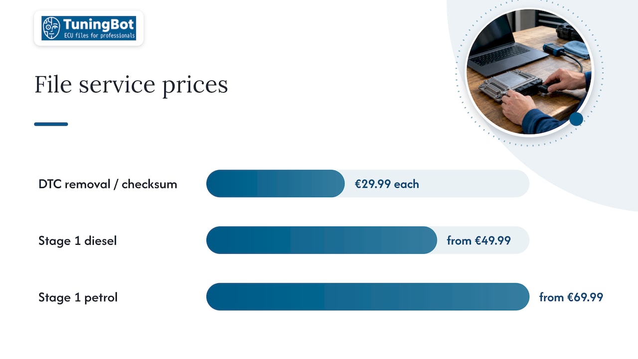
If your workflow involves a sensor change on an engine with a modified calibration, the cleanest path is to start from the original file read with your tool, state the hardware fitted, and specify the services you need. We list per-file pricing on our Liste de prix officielle du tuning ECU, including DTC removal and checksum correction at €29.99 each and Stage 1 files from €49.99 for diesel and €69.99 for petrol. Standard file orders do not require registration, and most standard files are delivered in approximately 15 to 20 minutes during published operating hours, depending on complexity and workload. Our wider tuning pages show what we cover by application.
FAQ
Can you calibrate a MAP sensor itself?
No. A MAP sensor is a fixed transducer, and what you calibrate is the ECU’s interpretation of its output. You define the voltage and pressure relationship in the ECU, then verify it against barometric pressure with the engine off and against a reference under load.
What is a normal MAP reading at key-on, engine-off?
It should be close to the local barometric pressure, because the sensor is absolute. About 100 kPa is typical near sea level, and lower at altitude or in low-pressure weather. All pressure sensors on the engine should agree with each other, which makes the check useful before you look at anything else.
Why does the ECU set a fault after I fit a larger MAP sensor?
The most common reason is that the error thresholds still reflect the old sensor. If the new sensor outputs a voltage that the ECU’s minimum or maximum limit treats as a short or open circuit, it flags a fault even though the sensor is healthy. Compare the new sensor’s output at its lowest and highest valid pressures with the error limits.
Do I need to recalculate checksums after changing MAP scaling?
On most ECU families, yes, since the scaling constants are part of the calibration data covered by the checksum. Correct the checksums before writing, and confirm the write with your tool’s verification step. Whether this applies to a given ECU depends on the family and software version.
Sources
- MAP Sensor 4.0 Bar Datasheet, Emtron Resource Centre
- MAP Sensor, GWv4 manual, Gems
- How to use Damos files in WinOLS, AutoExplain
- Pressure Sensors, Gears Magazine