
 EnglishEN
 DeutschDE
 EspañolES
 PortuguêsPT
 FrançaisFR
 РусскийRU
Rimappatura della TCU DSG richiede l'identificazione esatta del cambio, una coppia compatibile modelling, un file originale verificato, un metodo di programmazione supportato e procedure di adattamento specifiche per il cambio. Le unità DQ250, DQ381 e DQ500 non condividono una sequenza universale di flash, pressione o riapprendimento. I valori target di pressione, gli intervalli di temperatura dell’ATF, i codici IDE e le impostazioni del controllo di lancio devono essere ricavati dal software TCU esatto e dalla documentazione aggiornata dello strumento.
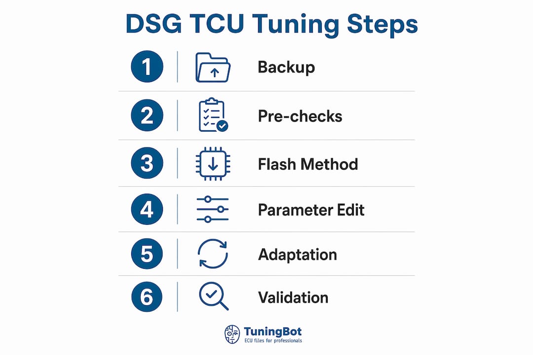
Istantanea del passaggio ordinato:
- Identificare la variante del cambio (DQ250, DQ381 o DQ500) e confermare il numero hardware della TCU.
- Eseguire il backup dei file binari originali della TCU e dell'ECU; verificare i valori checksum prima di procedere.
- Scegli il metodo di flashing: OBD, bench o boot, in base allo stato della TCU e al livello di rischio.
- Eseguire il flash della TCU con il file abbinato e sincronizzato.
- Cancellare tutti gli adattamenti della TCU e i codici di guasto immediatamente dopo la programmazione.
- Eseguire la sequenza di adattamento: IDE02294 → IDE02295 → IDE02298 (o equivalente specifico per la centralina) con ATF alla temperatura di esercizio specificata, motore in moto, piede sul freno.
- Completa un ciclo di guida misto città/autostrada per completare la calibrazione.
- Validare al banco prova e su strada rispetto ai criteri di accettazione.
Criteri di successo:
- Il dialogo di coppia tra ECU e TCU è sincronizzato; nessun flag di limitazione della coppia sul CAN.
- Le pressioni della frizione raggiungono i valori impostati senza slittamento a pieno carico.
- Al termine del ciclo di guida completo, non sono stati rilevati codici DTC relativi all'ingresso o alla trasmissione del sistema Limp-mode.
- I regimi di stallo del launch control e i tempi di cambiata si comportano come specificato nella calibrazione.
Cosa cambia effettivamente una mappatura della TCU del DSG e perché deve essere sincronizzata con la ECU?
La TCU controlla ogni aspetto del comportamento del cambio attraverso una serie di tabelle di calibrazione. Comprendere quali tabelle cambiano e perché devono essere allineate con la mappatura della coppia della ECU è la base per un'ottimizzazione sicura della trasmissione DSG.
Parametri regolati durante un TCU remap:
- Tabelle di richiesta di coppia e limite di coppia: Diverse tabelle limitano la coppia che la TCU accetterà dalla ECU; tutti i limiti pertinenti deve essere aumentato per evitare che il cambio limiti la potenza del motore.
- Tabelle obiettivo della pressione della frizione: Le pressioni massime della frizione di serie sulla piattaforma DQ250/DQ381 si trovano a livelli di fabbrica; le calibrazioni prestazionali le innalzano a valori superiori per gestire una maggiore coppia senza slittamenti.
- Pressione obiettivo della linea principale e pressione massima della linea: La pressione della linea è direttamente proporzionale al segnale di coppia ricevuto via CAN dalla ECU; aumentarla offre un margine per pressioni della frizione più elevate e richieste di corrente dei solenoidi.
- Limiti di corrente della frizione (corrente massima del solenoide): I limiti di corrente del solenoide 1 e del solenoide 2 devono essere ridimensionati quando i target di pressione della frizione aumentano, altrimenti i solenoidi non raggiungeranno la pressione comandata.
- Tabelle dei turni: Organizzate in base al cambio e alla modalità di guida modalità (ECO/Sport/Manuale/Tiptronic), queste tabelle definiscono i punti di cambio marcia in salita e in discesa. I dati relativi all'asse Z sono espressi in velocità del veicolo; conversione in giri motore L'uso della matematica dei rapporti di trasmissione per marcia rende la modifica dei punti di cambio molto più prevedibile.
- Tabelle di sovrapposizione delle frizioni: La maggiore sovrapposizione nel sistema Sport mode consente alla frizione secondaria di iniziare a innestarsi prima che la prima si disinnesti completamente, riducendo così il tempo di cambio marcia.
- Abilitazione/disabilitazione scalata marcia forzata: Un unico flag (con valori 0, 2, 3 o 7 a seconda del modello modalità) determina se le tabelle di cambio marcia forzato hanno la precedenza sulla tabella di cambio marcia principale nelle versioni TT e Sport del modello modalità.
- Flag di abilitazione del kickdown: Le colonne del kickdown per marcia nelle tabelle del programma di cambio vengono attivate o disattivate con un valore 0/1.
- Mappe della velocità di stallo (launch control): Questi valori definiscono il punto di mantenimento effettivo del numero di giri quando la frizione non è completamente innestata. Il regime di stallo del DSG deve essere sempre impostato a un valore inferiore rispetto al regime target launch control della centralina.
The ECU and TCU exchange torque information over the vehicle network. A mismatch between actual output, reported torque and TCU limits can cause torque intervention, poor clutch-pressure calculation or drivability problems.
Published torque limits for DQ250, DQ381 and DQ500 vary by hardware, clutch pack, software and vehicle application. Do not rely on one universal stock figure.
A TCU calibration may be useful where the stock gearbox strategy limits a remapped engine, but it is not automatically required on every Stage 1 vehicle.
Consiglio Pro: Always treat the TCU as the final arbiter of allowable torque. Raise TCU torque thresholds and line pressure targets before or simultaneously with ECU torque increases — never after. A TCU still running with stock limits will cap the ECU remap regardless of how well the engine file is calibrated.
Quali controlli in officina bisogna completare prima di effettuare il flashing di una TCU DSG?
Do not tune a transmission with unresolved clutch, hydraulic, mechatronics or electrical faults. Diagnose the gearbox and fluid condition first.
Mechanical checks:
- Inspect clutch condition; worn or contaminated clutch packs cannot reliably reach higher pressure targets and will slip under load.
- Assess mechatronics module health: check for internal resistance faults and solenoid response; a failing mechatronics unit will not respond correctly to new solenoid current limits.
- Verify DSG oil level and condition. Degraded or contaminated ATF reduces hydraulic efficiency and shortens clutch life after tuning. A full DSG fluid flush is strongly recommended before any remap if the fluid is discolored, smells burnt, or is past its service interval.
- Confirm no active mechanical DTCs related to clutch slip, gear engagement, or hydraulic pressure.
Electrical and vehicle checks:
- Connect a battery support unit and hold voltage above 13.5V throughout the flash process. A voltage drop during programming can corrupt the TCU binary and require bench recovery.
- Verify charging system health; a weak alternator that cannot sustain voltage under accessory load is a flash risk.
- Confirm the OBD communication link is stable and the vehicle is not in an active fault or limp-mode state before initiating a flash.
File and software checks:
- Read and record the TCU hardware number, software version, and VIN from the live unit.
- Record the ECU software version and hardware number to confirm file compatibility.
- Note all relevant checksums from the original read.
- Confirm the tuning tool firmware is current and supports the specific TCU variant being flashed.
- Verify that the TCU file received matches the recorded software version exactly — a version mismatch is a common cause of failed flashes and corrupted units.
Backup procedure:
- Perform a full OBD or bench read of the original TCU binary before any modification.
- Perform a full read of the original ECU binary.
- Run checksum verification on both files immediately after reading; store the verified originals with the vehicle VIN, date, and TCU/ECU software version in the filename.
- Keep a recovery plan documented: if OBD flash fails, which tool and method will you use for bench or boot recovery?
Consiglio Pro: Store original binaries in a version-controlled folder structure — one folder per vehicle, named with VIN and date. A technician who cannot locate the original file when a recovery is needed faces a bench flash at minimum and a TCU replacement at worst. File discipline is not optional.
Quali strumenti e metodi di flash-programming è consigliabile utilizzare per la TCU DSG remapping?
Tool selection and flash method determine workflow complexity, recovery options, and risk exposure. The right choice depends on the TCU variant, its current state, and the scope of changes being made.
Supported tools:
- Alientech KESS3: Covers OBD and bench protocols for a wide range of DSG TCU variants including DQ250, DQ381, and DQ500. Widely used for both initial reads and flashing. Firmware updates regularly expand supported variants.
- PCMFlash: Strong OBD coverage for VW AG TCUs; particularly well-regarded for DQ250 and DQ381 on MQB platforms. Module-specific protocols require the correct license.
- Magic Motorsport: Supports OBD and bench for multiple DSG variants; the Flex tool handles bench and boot protocols for units that cannot be reached via OBD.
- CMD: Covers bench and boot protocols; useful for recovery scenarios where OBD communication is unavailable or the TCU is in a degraded state.
- Dimsport: OBD and bench coverage for VW AG transmissions; the New Genius and New Trasdata platforms handle both read and write operations.
- AutoTuner: Supports OBD and bench flash for DQ250, DQ381, and DQ500 variants; the AutoTuner tool guide covers master/slave configuration and protocol selection in detail.
Flash method comparison:
| Metodo | Utilizzo tipico | Dipendenza principale | Attenzione |
|---|---|---|---|
| OBD | Supported in-vehicle programming | Stable vehicle network and protocol support | Not available for every TCU or software version |
| Panchina | Direct connection outside the vehicle | Correct pinout, adapter and power supply | ECU/TCU removal adds handling risk |
| Avvio / servizio Boot mode | Low-level access or recovery where supported | Processor-specific procedure | Not universal and not inherently lowest risk |
OBD, Bench and Boot each have different advantages and risks. Bench is not automatically safer than OBD, and Boot is not automatically the lowest-risk method.
File formats and checksum handling. Most DSG TCU files are delivered as binary (.bin) or encrypted container formats specific to the tool vendor. After any modification, checksum correction is mandatory before flashing. Checksum errors in a TCU file will cause the unit to reject the write or, in some cases, accept a corrupted calibration that produces unpredictable behavior. Use the checksum correction function built into your tuning software, or a dedicated validator, before every write operation.
Consiglio Pro: When raising line pressure or solenoid current targets significantly, prefer bench over OBD even if OBD is technically supported. A mid-flash interruption during a large-scale pressure table write is far more likely to require boot recovery than a routine shift-schedule edit. The extra setup time for bench is worth the reduced recovery risk.
Procedura dettagliata per la TCU DSG tuning destinata ai tecnici di officina
This is a general workshop framework only. DQ250, DQ381 and DQ500 procedures must be confirmed separately for the exact software version.
- Vehicle intake and VIN capture. Record VIN, odometer, and any existing DTCs. Photograph the current TCU and ECU software versions from a live scan tool read.
- Full backups with checksum verification. Read original TCU binary via OBD or bench. Read original ECU binary. Verify checksums on both files. Store with VIN and date.
- Record TCU ID and software version. Confirm the exact TCU part number and calibration software version. Cross-reference against the file set being applied to confirm compatibility. The ECU/TCU ID is the primary matching key for synchronized file delivery.
- Select or request synchronized ECU+TCU files. Confirm the ECU and TCU files are matched to each other’s torque targets. If ordering from TuningBot, upload both original binaries and specify the target power level and gearbox variant.
- Choose flash method and prepare tool. Set up KESS3, PCMFlash, AutoTuner, Magic Motorsport, CMD, or Dimsport per the method selected. Confirm tool firmware is current for the target TCU variant.
- Pre-flash validation and battery support. Connect battery support unit. Confirm voltage is stable above 13.5V. Clear any non-critical DTCs. Confirm no active communication faults.
- Flash the TCU. Write the verified, checksum-corrected TCU binary. Do not interrupt the process. Confirm successful write completion before disconnecting.
- Flash the ECU (if synchronized remap). Write the matched ECU binary using the same discipline. Confirm successful write.
- Reset and clear all TCU adaptations. Use the scan tool to clear all learned adaptation values. This step is not optional; without it, the TCU will attempt to apply new pressure targets against old learned offsets, producing incorrect clutch behavior.
- Execute the post-flash DSG adaptation sequence. See the relearn section below for the exact IDE sequence and environmental requirements.
- Controlled warm-up. Allow the vehicle to reach operating temperature under light load before any aggressive driving.
- Initial low-load drive test. Confirm basic gear engagement, no harsh shifts, and no DTCs before proceeding to dyno or high-load validation.
- Dyno and road validation. See the validation section for the full protocol.
Parameter change reference table:
| Parameter Area | What Changes | Direction | Note |
|---|---|---|---|
| Torque request limits | Multiple CAN torque cap tables | Raise | All relevant tables must be adjusted |
| Clutch pressure targets | Pressure target tables per mode | Raise | Stock ~15 bar → performance ~21 bar (DQ250/DQ381 example) |
| Main line pressure target | Hydraulic line pressure setpoint | Raise | Must provide headroom above clutch pressure targets |
| Solenoid current limits | Max current for Solenoid 1 and 2 | Raise | Required when clutch pressure targets increase |
| Shift schedule tables | RPM/speed-based upshift/downshift points | Adjust | Convert Z-axis vehicle speed to RPM for accuracy |
| Clutch overlap | Overlap duration per drive mode | Increase (Sport) | Reduces shift time; use conservatively |
| Stall speed (launch control) | RPM hold point pre-clutch engagement | Raise | Must remain below ECU launch control RPM target |
| Forced upshift enable | Mode flag (0/2/3/7) | Adjust | Disabling allows shift schedule to control TT/Sport |
| Kickdown enable | Per-gear 0/1 flag | Enable/disable | Per workshop and customer requirement |
Consiglio Pro: Update the ECU torque estimation maps to match the new torque targets so the CAN torque handshake remains accurate. If the ECU is reporting a torque value that does not reflect actual output after the remap, the TCU will set clutch pressure based on incorrect data, producing either slip or unnecessarily high clutch wear.
Come si esegue la sequenza di adattamento del DSG dopo la programmazione?
Post-flash adaptations may be required, but the exact procedure is gearbox- and software-specific. Repeating clutch adaptations after TCM reprogramming materially affects achievable clutch pressure and stall speeds; skipping it means the new setpoints never take effect in the learned values the TCU uses for daily operation.
Required environmental conditions before starting:
- ATF temperature must reach the specified operating temperature. Monitor via scan tool live data before initiating any adaptation command.
- Engine running, vehicle stationary, foot firmly on brake pedal.
- No active DTCs in the TCU.
- Stable battery voltage above 13.5V throughout the sequence.
Adaptation sequence (DQ250/DQ381 example):
- Identify the exact gearbox software and diagnostic tool.
- Check all prerequisites shown by the tool, including temperature, brake, engine and selector conditions.
- Run only the basic settings or adaptation routines specified for that unit.
- Confirm each routine reports successful completion.
- Clear only adaptation-related faults created by the procedure.
- Complete the prescribed relearn drive if required.
Box-specific notes:
- DQ250: The IDE02294/02295/02298 sequence is the standard post-flash adaptation path. Clutch adaptations must be completed after any programming event.
- DQ381: Adaptation sequences follow a similar structure but may require additional steps or different IDE codes depending on the specific software version. Confirm via the tool’s adaptation menu before proceeding.
- DQ500: The DQ500 uses a different adaptation architecture; consult the tool vendor’s documentation for the correct sequence. The ATF temperature window and the requirement to clear adaptations before running the sequence remain consistent.
Common pitfalls:
- Running adaptations before ATF reaches 50°C produces incorrect kiss point learning and will require the sequence to be repeated.
- Skipping IDE02294 and jumping directly to IDE02295 or IDE02298 causes incomplete adaptation; the TCU will not correctly establish the baseline before learning offsets.
- Using an unsupported OBD11 mode or a generic scan tool that does not support the specific IDE command set will appear to complete the sequence but will not execute the correct adaptation routines.
Consiglio Pro: Allow a 5–10 minute cool-down between the end of the IDE sequence and the start of the drive cycle. Immediately driving hard after the adaptation sequence, before the TCU has logged the initial kiss points, can produce harsh engagement and false slip counters in the first few minutes.

Come si effettua la rimappatura di una TCU DSG remap sul banco di prova e su strada?
Validation is the acceptance gate. A calibration that passes the step-by-step procedure but fails validation requires a return to the parameter tables, not a delivery to the customer.
Dyno protocol:
- Warm the vehicle to full operating temperature before any loaded pull.
- Begin with low-load, partial-throttle pulls in each gear to confirm basic shift behavior and absence of harsh engagement.
- Progress to full-throttle pulls, logging ATF temperature, clutch current, clutch pressure target vs. actual, CAN torque request vs. actual, and TCU diagnostic codes simultaneously.
- Confirm line pressure under full load matches the set target within an acceptable tolerance.
- Check for clutch slip counters in TCU live data during and immediately after each pull.
- If launch control is enabled, perform controlled launch tests and verify stall speed behavior matches the calibrated target.
Road test profiles:
- Low-load city drive: Confirm smooth engagement from rest, no shudder, and correct upshift behavior in ECO/Normal mode.
- High-load acceleration runs: Full-throttle acceleration in Sport and Manual modes; confirm shift times are within target and no torque-limiting flags appear.
- Highway/gear-hold check: Confirm forced upshift behavior (or its absence if disabled) and kickdown response at highway speeds.
- Launch control check (if enabled): Verify stall speed, clutch engagement feel, and absence of slip codes post-launch.
Pass/fail criteria:
- No clutch slip indicated in TCU slip counters after any test run.
- Recorded line pressure matches set targets under full load.
- No torque limit flags on CAN during any test condition.
- Gear engagement times within the target shift times specified in the calibration.
- ATF temperature remains within safe operating range throughout the test sequence.
- Zero transmission DTCs after the complete drive cycle.
Monitoring channels to log throughout validation:
- ATF temperature
- Clutch current (Solenoid 1 and 2)
- Clutch pressure target vs. actual
- CAN torque request vs. actual engine torque
- TCU diagnostic fault codes
- Engine torque limiting flags from ECU
If any metric fails, return to the parameter tables. Check the torque handshake calibration first, then consider incrementally increasing line pressure or clutch current targets within safe margins. For broader performance build context and post-tune vehicle dynamics checks, including alignment and suspension setup after powertrain changes, consulting a specialist is advisable before track or high-load use.
Cosa causa i problemi al DSG dopo la rimappatura e come si risolvono?
Most post-flash failures trace back to one of four root causes: mismatched torque handshake, incomplete adaptation, incorrect pressure targets, or a pre-existing mechanical fault that the remap exposed.
Symptom-to-action diagnostic pairs:
- Clutch slip under high load: Confirm line pressure targets and clutch current limits are correctly raised. Verify clutch adaptations were completed post-flash. If adaptations are correct and slip persists, the clutch packs may be worn beyond the point where higher pressure can compensate.
- Rough or harsh shifts: Check shift schedule tables for colliding upshift/downshift points. Review clutch overlap settings; excessive overlap in Normal mode produces harsh engagement. Confirm the adaptation sequence completed correctly.
- Limp-mode or torque-limited behavior: Read DTCs immediately. Verify TCU torque limit tables are raised to match ECU output. Confirm the CAN torque handshake is synchronized; a mismatch between ECU-reported torque and TCU torque limits is the most common cause of limp-mode entry after a remap.
- Incorrect launch behavior or stall speed: Inspect stall speed maps. Confirm the DSG stall speed target is set below the ECU launch control RPM value. Check launch-specific clutch pressure and torque limit tables.
- No improvement after flash: Confirm the correct file was written to the correct unit. Read back the flashed TCU and compare checksums against the intended file. A failed write that the tool reported as successful is rare but possible.
Troubleshooting flow:
- Read all DTCs from TCU and ECU.
- Review logged CAN torque values and clutch current from the validation drive.
- Run the adaptation sequence again if kiss points or clutch duty positions appear incorrect.
- Re-flash a conservative TCU file if data corruption is suspected.
- If OBD communication is unavailable or unstable, proceed directly to bench flash for recovery.
Consiglio Pro: Use trend logging across multiple drives and compare pre-flash and post-flash logs side by side. Isolating whether a behavior change is parameter-driven or adaptation-driven is much faster when you have a clean baseline log from before the flash. A single post-flash log without a pre-flash reference makes root-cause analysis significantly harder.
Supporto file ECU e TCU di TuningBot
TuningBot supports ECU and TCU file calibration where the exact gearbox, software and file format are covered. A standalone TCU file or matched ECU+TCU set may be appropriate depending on the job.
Prima di ordinare, le officine possono verificare Copertura servizi ECU e TCU, rivedi il Listino Prezzi Pubblico e naviga tra i disponibili Servizi di modifica.
I file possono essere inviati tramite Rimappa il tuo file without prepaid credits. The workshop remains responsible for mechanical checks, supported programming, adaptations, legal compliance and final validation.
Punti chiave
A correct DSG TCU workflow requires exact identification, a compatible file, supported programming, box-specific adaptations where required and measured validation.
| Punto | Dettagli |
|---|---|
| Backup and checksum first | Read and verify checksums on both ECU and TCU originals before any flash operation. |
| Synchronize torque targets | Raise TCU torque limits and line pressure simultaneously with ECU torque increases to prevent CAN limiting loops. |
| Adaptation sequence is mandatory | Run IDE02294 → IDE02295 → IDE02298 (or box-specific equivalent) at 50–60°C ATF; skipping it means new setpoints never take effect. |
| Match flash method to risk | Use bench or boot for large-scale pressure/current changes; OBD for routine remaps on healthy, stable units. |
| TuningBot matched file delivery | Upload original ECU and TCU binaries to TuningBot for synchronized file bundles with checksums, change logs, and post-delivery refinement support. |
Cosa si impara davvero in officina sul DSG tuning
Mechatronics health should be evaluated using the correct diagnostic and manufacturer procedures. Direct resistance measurement is not a universal or sufficient test for every DSG unit.
ATF condition and service history matter, but fluid replacement or flushing should follow the gearbox manufacturer’s procedure and is not automatically required before every tune.
On the calibration side, the pattern that produces the best results consistently is a conservative first stage. A workshop that validates a moderate torque increase through the full acceptance protocol, confirms clutch pressures are stable, and then moves to the final target has a documented audit trail and a vehicle that has proven its mechanical readiness. A workshop that flashes the final target file immediately and then troubleshoots slip has no baseline to work from.
Version control matters more than most technicians realize. Keeping a folder per vehicle with the original binary, the flashed binary, the change log, and the validation log creates an audit trail that protects the workshop in any dispute and makes refinement requests faster and more accurate. The technician who can send TuningBot a complete file history gets a faster, more precise revision than one who sends only a description of the symptom.
Supporto file ECU e TCU di TuningBot
TuningBot supports ECU and TCU file calibration where the exact gearbox, software and file format are covered. A standalone TCU file or matched ECU+TCU set may be appropriate depending on the job.
Prima di ordinare, le officine possono verificare Copertura servizi ECU e TCU, rivedi il Listino Prezzi Pubblico e naviga tra i disponibili Servizi di modifica.
I file possono essere inviati tramite Rimappa il tuo file without prepaid credits. The workshop remains responsible for mechanical checks, supported programming, adaptations, legal compliance and final validation.
Fonti utili per i comandi specifici dei box e i codici degli IDE
Technicians working on DQ250, DQ381, and DQ500 variants should keep the following references on hand for adaptation ID mappings, shift schedule conversion, and tool-specific protocols.
- COBB MQB 7-Speed DSG Tuning Guide — technical reference; verify against exact software.
- EcuTek TCM adaptation reference — tool-specific reference.
- C7Wiki DSG adaptation page — community reference; not universal or official.
- Guida alla configurazione delle prestazioni E6 Carbon — general build context.
- TuningBot TCU tuning applications — internal TuningBot reference.
| Resource | Uso primario | Box Coverage |
|---|---|---|
| c7wiki DSG Adaptation | IDE sequence and ATF temp requirements | DQ250, DQ381 |
| ECUTek DQ250 Wiki | Torque limits, clutch pressure, solenoid scaling | DQ250 |
| COBB MQB DSG Guide | Shift schedule editing, speed-to-RPM conversion | DQ250, DQ381 |
| TuningBot DSG Blog | Synchronized file workflow, torque limit context | DQ250, DQ381, DQ500 |
| TuningBot TCU Examples | Validation reference, real-world parameter examples | DQ250, DQ381, DQ500 |
Keep copies of any IDE codes and vendor adaptation commands used in the workshop file versioning folder for each vehicle. Traceability of which adaptation sequence was run, on which software version, is essential for refinement requests and post-delivery support.
FAQ
È necessaria una modifica della TCU per i guadagni della ECU di Stage 1?
Not always. It is useful when stock gearbox limits, shift strategy or torque reporting interfere with the engine calibration.
Una modifica alla TCU fa una differenza misurabile nel comportamento del cambio?
It can change shift schedules, torque intervention, clutch control and launch behavior. Results depend on the gearbox software and condition.
È possibile effettuare la rimappatura di una trasmissione DSG indipendentemente dalla centralina motore (ECU)?
Yes. If engine torque has also changed, ECU and TCU torque reporting should be checked together.
Una rimappatura della TCU aumenta la potenza?
No. It does not create engine power, though it may reduce transmission-side limiting.
Quanto tempo richiede la procedura completa per la TCU DSG tuning?
Time varies by access method, backup, adaptations, validation and revisions. There is no universal duration.