

 EnglishEN
 ItalianoIT
 DeutschDE
 EspañolES
 PortuguêsPT
 РусскийRU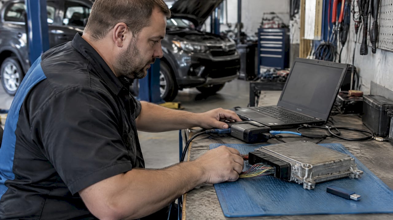
PCMflash bootloader tuning starts with identifying the ECU and selecting its documented programming method. PCMflash handles supported reading and writing operations; calibration changes require a suitable editor or file workflow. Boot, bench and OBD access are protocol choices, not universal rankings of safety.
PCMflash bootloader tuning starts with module support
Record the ECU hardware number, software identifier, vehicle application and selected PCMflash module. Check the current support entry and connection instructions for the exact operation. Support for identification does not automatically include reading, writing, EEPROM access or recovery.
Confirm the software license, adapter and required accessories before connecting the ECU. J2534 describes an interface standard, but a J2534 label alone does not establish compatibility with every PCMflash module. Some operations require particular Scanmatik hardware or additional control connections.
The official download page provides module-specific diagrams. Use those instructions for the selected module rather than a connector image from a different ECU with a similar housing.
Distinguish boot, bench and OBD access
OBD describes access through the vehicle diagnostic connection. Bench generally describes a direct connection to a removed controller, often without opening its housing. Boot access can require opening the ECU and making additional connections. The actual meaning and procedure must come from the tool documentation.
Boot access is not automatically safer than OBD. Opening, probing and reconnecting introduce their own risks, while an OBD operation depends on the vehicle electrical and communication environment. Choose the supported method for the identified ECU and task.
Identify what the saved file contains
Save the identification result and every supported original read before making changes. Distinguish a physical read, a calibration-only read and a virtual stock file supplied for a software identifier. None should be described as a complete backup unless its memory coverage supports that description.
Record the file format, size and origin. A BIN extension alone does not establish memory coverage; a container may need a documented export or conversion process. An expected file size is a useful check, but it cannot prove that the content is correct.
Keep an untouched copy separate from the working file. If the tool cannot read a region needed for recovery, resolve that limitation before relying on the saved file as a recovery plan.
Assign checksum handling to the supported workflow
Check whether the selected protocol verifies or corrects the relevant integrity data and at what stage. There is no universal standalone command to run every edited file through PCMflash for correction. Follow the module instructions and retain any messages shown during file selection or writing.
A matching checksum does not establish correct map addresses, suitable calibration values or compatibility with another software build. Checksums and digital signatures also serve different purposes. Do not assume that correcting one makes an unsupported file acceptable.
When requesting a file modification, state which tool, module and read method produced the file. Checksum correction should be explicitly assigned to the tool or purchased service; it is not automatically included with every TuningBot file order.
Use the specified electrical setup
Use the power supply, wiring, switching sequence and voltage range specified for the vehicle and tool procedure. There is no single voltage value suitable for every bench ECU or in-vehicle programming operation. Confirm polarity, grounds and connector seating before applying power.
A Powerbox or similar accessory can help with supported power-control functions, but its presence does not establish that the harness or settings are correct. Keep the programming computer stable and avoid changing drivers or disconnecting interfaces during an active operation.
Treat a failed write as a documented recovery task
Record the exact error, operation stage and current ECU response. Follow the on-screen instruction for power and ignition state; neither immediately cycling power nor leaving it unchanged is a universal recovery rule. Do not switch access modes or repeatedly write unrelated files by trial and error.
Use the supported recovery function or obtain instructions from the tool supplier with the session logs and ECU identification. Recovery is not guaranteed by possession of an original calibration read.
After a successful write, confirm identification and diagnostic communication, review faults and carry out the application-specific checks. Read-back comparison is useful only where supported and where the returned data represents comparable memory regions.
Questions fréquemment posées
Does every PCMflash module support every J2534 adapter?
No. Adapter requirements depend on the module and operation. Check the specific support entry and connection instructions.
Is a PCMflash read always a full ECU backup?
No. Read coverage varies, and a virtual read or calibration-only file is not a complete copy of every memory region.
Should a failed write always be retried in boot mode?
No. Follow the documented recovery procedure for the selected protocol and preserve the error and session information.
Sources and further reading
- What Is PCMflash? | High Performance Academy
- PCMflash
- J2534-1_0500_202201: Recommended Practice for Pass-Thru Vehicle Programming – Recommended Practice
- PowerBox for PCMflash
- Vehicle Diagnostics Gladstone | Advanced Fault Finding
- Battery Voltage & J2534 Programming – Diagnostic Network
- some models specifying tighter ranges
- PCMflash: official downloads and connection diagrams