

 EnglishEN
 ItalianoIT
 DeutschDE
 EspañolES
 FrançaisFR
 РусскийRU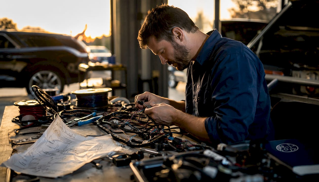
ECU harness modification is the redesign, repair or replacement of the wiring loom that connects the engine control unit to sensors, actuators, power supplies and vehicle networks. It is not a cosmetic change: wiring quality directly affects signal integrity, sensor accuracy, actuator control and the reliability of every calibration written to the ECU. The work may involve repairing an OEM loom, repinning connectors for an engine swap or building a fully custom motorsport harness around a standalone or production ECU.
What is ECU harness modification and why does it matter?
ECU harness modification covers two distinct approaches: reworking an existing factory loom or building a fully custom standalone harness from scratch. Each approach serves a different build profile, and choosing the wrong one wastes time and money. The industry terms for these approaches are “factory harness rework” and “standalone custom harness build.”
Reworking a factory harness preserves OEM sensor compatibility and costs less when the original loom is in good condition. It works well for mild engine swaps where the donor ECU pinout closely matches the target vehicle. The downside is that factory looms carry circuits for systems you may have deleted, such as air conditioning, cruise control, or emissions hardware, and those dead circuits add weight and diagnostic complexity.
A standalone custom harness eliminates every unused circuit. Standalone harnesses are tailored to specific ECU pinouts and chassis integration points, which produces cleaner installations, fewer faults, and easier tuning. They are the standard choice for dedicated motorsport builds, complex engine swaps, and any application where long-term reliability outweighs upfront cost.
Dica de Mestre: Before committing to either approach, map every sensor and actuator your ECU requires against the existing loom. That audit reveals whether a factory rework is viable or whether a full custom build is the only logical path.
What types of connectors and materials meet professional standards?
TXL and GXL are common automotive wire specifications for engine-bay use, but they are not the only acceptable choices. Professional harness builders may also use cross-linked automotive wire such as SXL, Tefzel/ETFE or OEM-specific cable depending on temperature, abrasion, flexibility and motorsport requirements.
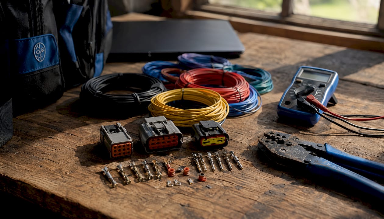
Wire gauge selection is not optional. Undersized wire causes voltage drop and heat buildup, both of which degrade sensor signals and create intermittent faults that are difficult to diagnose. The correct gauge depends on current load, circuit length, and ambient temperature. A power feed to a fuel injector driver requires heavier gauge than a 5V reference signal to a MAP sensor.
Connector selection is equally critical. The following connector families are the professional standard for ECU harness work:
- Deutsch DT and DTM series: sealed, robust connectors commonly used for motorsport and auxiliary engine-bay circuits; current rating depends on terminal size and family.
- TE/AMP Superseal and MCP families: widely used sealed automotive connectors for sensors, solenoids and OEM-style interfaces.
- OEM ECU connector systems: Bosch, Delphi, Denso, Yazaki, Sumitomo, Molex and TE housings must use the exact matching terminal, seal and secondary lock.
- Autosport connectors: Deutsch AS, Souriau 8STA and similar circular connectors suit high-end motorsport harnesses where packaging, serviceability and low weight justify the cost.
Improper connectors cause intermittent electrical faults that appear under load and disappear at rest, making them the hardest category of fault to diagnose on a running vehicle. Spending correctly on connectors at the build stage eliminates that diagnostic burden entirely.
Dica de Mestre: Always source connectors with matching terminal plating. Mixing gold-plated pins with tin-plated sockets creates galvanic corrosion over time, which degrades contact resistance and produces ghost signals in sensitive sensor circuits.
How are ECU connector terminals repaired or repinned correctly?
Terminal repair is the most technically demanding part of an ECU wiring upgrade. The correct method uses a dedicated terminal extraction tool sized to the specific connector family. Releasing secondary locks before depressing the primary retention lance is the correct sequence. Skipping this step damages the plastic housing and makes the connector unreliable even after the pin is replaced.
The process for professional terminal repinning follows this sequence:
- Identify the connector family and terminal size. ECU connectors from Bosch, Delphi, and Denso each use proprietary terminal dimensions and locking systems.
- Release the terminal position assurance (TPA) or secondary position assurance (SPA) lock using a small flat pick. Do not force it.
- Insert the correct extraction tool into the terminal cavity and depress the retention lance. Apply steady, light pressure. The terminal releases without cutting the wire.
- Slide the terminal out from the rear of the connector. Inspect the cavity and the wire crimp for damage.
- Install the OEM-equivalent replacement terminal. Match the plating, crimp barrel dimensions, and locking tab geometry exactly.
- Seat the terminal until the retention lance clicks. Reinstall the TPA or SPA lock.
Repinning is preferable when the connector and terminal are serviceable, but a correctly engineered splice is not automatically unreliable. OEM-approved open-barrel crimps, sealed butt splices or ultrasonic welds can be appropriate when positioned and strain-relieved correctly. Uncontrolled solder-and-tape repairs are the real problem.
The partner resource at Underground Dynamics illustrates how precision component selection at the drivetrain level mirrors the same discipline required in harness work. Correct specification matters at every layer of a performance build.
Dica de Mestre: Label every terminal with its circuit function before extraction. ECU connectors with 80 or more pins become impossible to reassemble correctly without a circuit-level record of each cavity.
What best practices improve reliability in ECU harness builds?
Reliability in a custom ECU harness comes from four disciplines: connection method, shielding, grounding, and documentation. Each one is non-negotiable in a professional build.
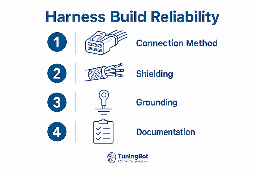
Solder can create a rigid transition that is vulnerable to fatigue when it wicks into flexible wire and lacks strain relief. For most engine-bay harness work, OEM-style open-barrel crimps are preferred. Properly executed solder joints can still be valid in specific low-vibration or repair situations when supported and sealed correctly.
Shielding. Signal wire shielding prevents electromagnetic interference from corrupting sensor data. Unshielded knock sensor, wideband O2, and MAF wiring routed near ignition coil feeds picks up radiated noise that the ECU interprets as real sensor variation. That noise produces tuning errors and false knock events under load.
Sensitive analog sensors require grounding exactly as specified by the ECU or sensor manufacturer. Many wideband controllers use separate sensor, analog and power grounds; tying them incorrectly to chassis or ECU grounds can create offsets. The correct topology must follow the hardware documentation rather than a universal rule.
Documentation. Labeled branches, color coding, and wiring diagrams convert a complex harness into a manageable diagnostic resource. A tuner or mechanic who did not build the harness can trace any circuit in minutes when the documentation is complete. Without it, fault-finding on a custom harness can take hours and still produce inconclusive results.
For tuners working with Continental ECU platforms, the Guia de arquivo ECU Continental covers pinout-specific considerations that directly affect harness connector assignments.
How does ECU harness modification support tuning and performance?
A correctly modified harness is the physical foundation that makes advanced ECU tuning possible. Every calibration table in an ECU file depends on accurate sensor inputs. If the harness delivers corrupted or intermittent signals, the calibration cannot perform as intended regardless of how well the remap file is written.
“Poor wiring is the leading cause of intermittent faults and fire hazards in performance builds. Wiring quality is as critical as mechanical and tuning work for long-term build reliability.” ECU Wiring Auckland Expert Guide
Standalone harnesses aligned to specific ECU pinouts make engine swaps tractable. A builder running a Bosch Motronic standalone ECU in a chassis it was never designed for needs every sensor and actuator wired to the correct pin with the correct signal type. Mismatched pinouts produce DTCs, limp mode events, and in some cases, actuator damage. The engine ECU programming guide covers how pinout alignment affects programming steps and tool compatibility.
Clean, documented harnesses also reduce long-term maintenance costs. A workshop that services a well-documented custom harness spends a fraction of the diagnostic time compared to one tracing an undocumented loom. That efficiency translates directly to lower labor costs and faster turnaround for the vehicle owner.
Principais Conclusões
ECU harness modification is the electrical foundation of every reliable performance build, and the quality of materials, connectors, and documentation determines whether the tuning above it can perform correctly.
| Ponto | Detalhes |
|---|---|
| Two core approaches | Factory harness rework suits mild swaps; standalone custom builds suit motorsport and complex engine swaps. |
| Material standards | Use automotive-grade TXL or GXL wire and Deutsch DT, DTM, or Superseal connectors to prevent faults. |
| Terminal repair method | Use extraction tools and OEM-equivalent terminals. Never cut and splice ECU signal circuits. |
| Crimp over solder | Open-barrel crimps with heat-shrink seals outperform solder joints in high-vibration engine bay locations. |
| Documentation is mandatory | Labeled branches, color coding, and wiring diagrams reduce diagnostic time and improve serviceability. |
Why wiring discipline separates reliable builds from problem builds
The TuningBot Technical Team has reviewed hundreds of ECU tuning files submitted by workshops where the underlying fault was not in the calibration. It was in the harness. A remap file calibrated correctly against a Bosch EDC17 or a Marelli MJD platform cannot compensate for a wideband O2 sensor running on a shared chassis ground. The lambda signal drifts, the closed-loop fueling chases a ghost, and the tuner spends hours adjusting tables that were never the problem.
The most common mistake we see from enthusiasts attempting DIY harness work is undersized wire on injector feeds. The voltage drop under high-duty-cycle injection events causes the injector to open late and close early. The ECU sees the commanded pulse width, not the actual delivered pulse, and the fuel model becomes inaccurate at exactly the load points where accuracy matters most.
Serviceability is the other discipline that separates professional harness work from amateur builds. A harness built with no documentation is a liability. The builder who made it may not be available when the fault appears two years later. A fully documented harness with labeled branches and a printed wiring diagram is an asset that transfers with the vehicle and reduces every future diagnostic session to a straightforward process.
DIY harness work is achievable with the right tools and materials. The professional advantage is not access to secret techniques. It is the discipline to follow correct process at every step, from connector selection through final documentation.
— Equipe Técnica do TuningBot
TuningBot’s ECU calibration support for custom harness and engine-swap projects
TuningBot supports workshops working with modified OEM harnesses, engine swaps and custom ECU installations where the underlying ECU file remains compatible with a supported production control unit. The wiring must be complete and electrically correct before calibration begins: software cannot compensate for wrong pinouts, unstable grounds or corrupted sensor signals.
Antes de pedir, oficinas podem verificar Cobertura do serviço de ECU, revise Lista de preços pública e navegue pelos disponíveis Serviços de ECU.
Once the harness, ECU identification and diagnostic data are confirmed, the original file can be submitted through Remapeie seu arquivo without purchasing prepaid credits. TuningBot supports common tools including Alientech KESS3, AutoTuner, Magic Motorsport, CMD, Dimsport and PCMFlash.
Para orientação técnica relacionada, consulte o Engine ECU Programming Guide e o Continental ECU File Guide.
PERGUNTAS FREQUENTES
O que é a modificação do chicote da ECU, em termos simples?
A personalização do chicote elétrico da ECU (modification) é o processo de adaptar ou reconstruir o chicote elétrico que conecta a unidade de controle do motor aos sensores e atuadores do veículo. Esse processo abrange desde a adaptação de um chicote de fábrica até a construção de um chicote elétrico totalmente personalizado e independente para uma combinação específica de ECU e motor.
Quando devo construir um chicote independente em vez de retrabalhar o chicote de fábrica?
Construa um chicote elétrico independente quando o chicote original da fábrica tiver circuitos demais sem uso, quando a configuração de pinos da ECU não corresponder ao chassi original, ou quando a montagem for destinada ao uso em esportes motorizados. Os chicotes elétricos independentes eliminam os circuitos sem uso e resultam em instalações mais organizadas e confiáveis.
Quais conectores são padrão para trabalhos profissionais em chicotes de ECU?
Professional harnesses use connector systems matched to the current, sealing, temperature and packaging requirements. Common families include Deutsch DT/DTM, TE Superseal/MCP, Bosch, Delphi, Yazaki, Sumitomo and motorsport-grade Autosport connectors.
Por que devo evitar soldas em chicotes no compartimento do motor?
OEM-style crimps are generally preferred because they preserve wire flexibility and are easier to reproduce consistently. Solder is not universally forbidden, but it must be used with correct strain relief, sealing and vibration control.
How does ECU harness quality affect tuning results?
Poor power supply, grounding, shielding or terminal contact can corrupt sensor and actuator behavior, making calibration data unreliable. A stable, documented harness is therefore a prerequisite for accurate ECU tuning and diagnostics.