

 EnglishEN
 DeutschDE
 EspañolES
 PortuguêsPT
 FrançaisFR
 РусскийRU
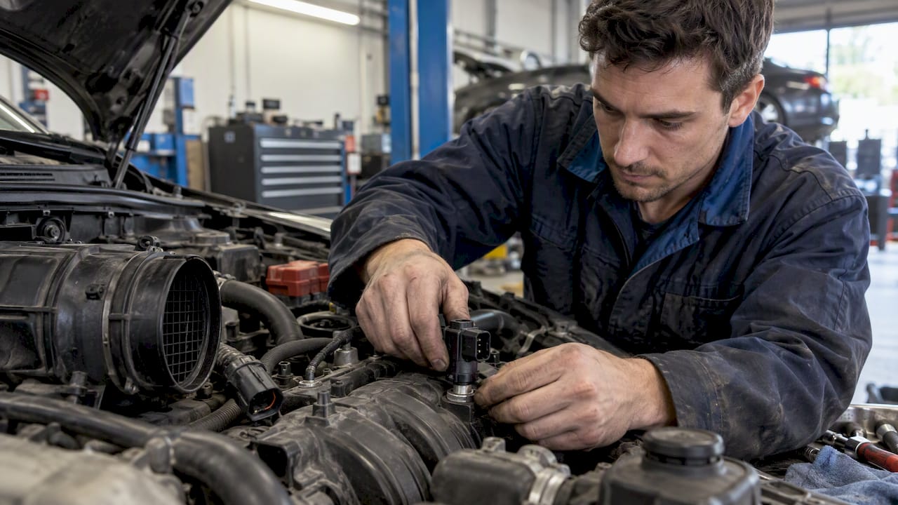
Speed density conversion changes how an ECU determines engine air charge, using a pressure-based model instead of relying on a MAF signal for the operating regions being converted. A useful conversion addresses a measured limitation and uses software that supports the intended strategy. Removing the sensor alone does not create a calibrated air model.
Speed density conversion: understand the air model
A typical model uses manifold absolute pressure, engine speed, displacement, a charge-temperature estimate and volumetric efficiency. The ECU estimates cylinder air mass, then combines that estimate with fuel targets and injector characterization. The names, units and structure of the calibration tables vary by controller.
Il rusEFI documentation illustrates an implementation with a modeled charge temperature. Its use of intake and coolant temperatures should not be presented as a universal formula for every ECU. A sensor reading and the temperature used internally for air-mass calculation may differ.
VE represents the model’s description of cylinder filling. Its calibrated values can also reflect the conventions of the particular ECU model; they should not be transferred between unrelated systems solely because displacement is similar.
Establish whether conversion solves the problem
Before replacing MAF-based control, distinguish sensor saturation, incorrect scaling, wiring faults, intake leaks and flow disturbances. A larger sensor housing may change both the transfer characteristic and usable resolution. Speed density is one possible strategy, not an automatic improvement for every modified engine.
High-overlap camshafts can complicate both approaches: reversion can disturb a MAF signal, while unstable manifold pressure can reduce the usefulness of a simple MAP-based model. Some controllers support blended or alternative load models. That capability must be established for the actual software rather than inferred from another vehicle.
The retained High Performance Academy conversion lesson e HP Tuners speed-density webinar provide platform-oriented training context. Neither replaces the relevant ECU and editor documentation.
Verify MAP, temperature and wiring
MAP is absolute pressure, not boost pressure relative to the surrounding atmosphere. Confirm the sensor’s pressure range, voltage transfer function, reference supply and ground. The ECU input must support the expected operating range without clipping. Selecting an unnecessarily wide-range sensor can also affect usable resolution.
With the engine stopped and pressures equalized, compare MAP with a suitable local pressure reference. A weather-service value corrected to sea level is not necessarily the pressure at the vehicle. Check readings at additional known conditions where the equipment and sensor documentation allow it; a single point cannot validate an entire transfer curve.
Consider the IAT sensor’s original location and electrical integration before altering the intake. If IAT was built into the MAF assembly, its function still needs a supported solution. This engine-sensor overview from Apex Tech Nation is useful background; use the sensor manufacturer’s data for actual scaling and installation.
An IAT rise during idling followed by a fall at speed does not by itself prove a bad installation. Real charge heating, sensor response and the ECU’s heat-transfer model all contribute. Compare the reading with operating conditions before changing placement or compensating in the VE table.
Calibrate the model without hiding other faults
Establish fuel type, injector characterization, fuel-pressure behavior and reliable lambda measurement before interpreting fuel error as a VE error. Exhaust leaks, misfire, transient enrichment and fuel trims can distort that interpretation. Do not reshape the air model to disguise a mechanical or measurement fault.
Use a supported base calibration for the identified combination, then validate stable operating regions under controlled conditions. The correct way to interpret commanded and measured lambda depends on which corrections and learning functions are active. A simple proportional VE adjustment is not valid for every sample or ECU strategy.
Record the state of closed-loop control, learned corrections and operating modes. Evaluate transitions separately from steady operation, including starting, warm-up, acceleration and deceleration. Where variable valve timing changes cylinder filling, the model may need to account for cam position rather than use one table for all states.
Related explanations are available in the fuel-map guide, VVT guide e spark advance guide. Avoid using ignition changes to conceal incorrect fueling or unstable load calculation.
Confirm software support and file integrity
Some ECUs support speed density through existing settings; others use combined airflow models or require software changes outside ordinary calibration. Do not assume that disabling a MAF diagnostic activates the intended load model. Removing a fault code can hide a problem without changing the underlying control strategy.
Identify which functions still use the MAF signal, including diagnostics or plausibility checks. Physical removal should follow the verified system design. A retained sensor may remain useful even when it is not the principal load input.
Preserve the original file and record its read method and coverage. Follow the tool’s supported write workflow and verify checksum responsibilities. A checksum result does not validate the air model or establish that a modified firmware is compatible.
Validate across conditions and define the job
Check more than a successful full-load run. Starting, heat soak, idle, load transitions, fuel-pressure behavior and changes in ambient conditions can expose weaknesses that a single dyno session misses. The required test coverage depends on the vehicle and intended operation; one additional day is not a universal acceptance test.
A speed-density label is not evidence of emissions compliance. Retain the EPA policy and historical investigation references below as context, and assess the actual changes under applicable requirements. The emissions compliance guide explains why supporting evidence matters.
When requesting file work, describe the ECU identity, sensor part numbers, hardware changes, existing strategy and available logs. Confirm the specific scope and current service terms; software support, calibration validation and hardware installation are separate tasks.
For a manufacturer example, see Haltech’s VE setup documentation; its requirements apply to the documented system.
Domande frequenti
What is a speed density conversion?
It changes the air-charge strategy to a pressure-based model in the relevant operating regions. A typical model uses MAP, engine speed, charge temperature and volumetric efficiency.
Is speed density always better than a MAF?
No. Both approaches have limitations. The choice depends on measured sensor behavior, engine characteristics and supported ECU strategies.
Must the MAF sensor be physically removed?
Not necessarily. The sensor may still serve other functions or participate in a blended strategy. Confirm the complete software and wiring design first.
Does high IAT after idling prove incorrect sensor placement?
No. Actual charge heating, sensor response and model behavior can all contribute. Compare measurements with operating conditions before deciding the cause.
Can fuel trims validate the entire VE model?
No. Corrections at one operating point do not establish accuracy across starting, transients, different load regions or environmental conditions.