

 EnglishEN
 DeutschDE
 EspañolES
 PortuguêsPT
 FrançaisFR
 РусскийRU
PCMflash ECU calibration steps should be treated as a tool-specific programming workflow, not as a universal rule that every ECU must be read in full, checksum-corrected twice, or recovered through Bench/Boot. PCMflash is primarily a read/write and protocol platform; the exact source-file type, adapter, module license, checksum handling, VID/VIN behavior and recovery method depend on the control unit and PCMflash module being used. A professional workflow starts with exact ECU identification, current module documentation, stable power and a source file appropriate to that protocol.
PCMflash ECU calibration steps follow a robust workflow: identify the ECU and PCMflash module → confirm access method and power requirements → preserve the supported source file → calibrate in the appropriate editor → use the module-specific integrity/write process → validate the vehicle after programming.
Before touching a vehicle, confirm you have:
- Confirm the exact PCMflash module/license and the ECU/TCU operation it supports.
- Use a supported J2534 or vendor-recommended interface and current drivers.
- Record ECU/TCU hardware and software IDs before selecting the protocol.
- Preserve the source file produced by the supported read, virtual or server workflow.
- Use the regulated power conditions specified by the protocol/tool documentation.
- Know the supported recovery procedure before starting the write.
Consiglio Pro: Record your Guardant dongle serial number in your job file before every session. There’s no local backup for that key, and losing it mid-job means losing access to every activated module until the vendor resolves it.
Preserve the source file, record the PCMflash module/license context and confirm stable programming conditions before any write.
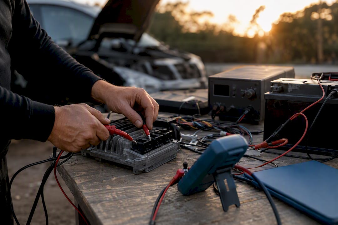
PCMflash ECU Calibration Steps: Key Takeaways
Reliable PCMflash ECU calibration steps depend on exact module support, correct interface/power setup, source-file traceability, protocol-specific integrity handling and post-write diagnostics.
| Punto | Dettagli |
|---|---|
| Module support comes first | Confirm the exact PCMflash module, ECU/TCU and supported operation before connecting. |
| Read type is protocol-specific | Full, partial, virtual, Bench and Boot workflows are not interchangeable. |
| Never overwrite the source file | Keep source and edited/release revisions clearly separated. |
| Checksum handling is not “twice by rule” | Use the checksum/signature/integrity procedure required by the exact module and write workflow. |
| Recovery is tool-specific | Do not assume Bench or Boot is always the next step after an OBD failure. |
| Validate after programming | Check communication, DTCs and the parameters affected by the calibration before vehicle release. |
PCMflash ECU Calibration Steps: Hardware and Software Prerequisites
Many failed sessions originate before programming: wrong module selection, unsupported adapter/driver, unstable power, incorrect source-file type or incomplete ECU identification.
PCMflash licensing uses Guardant-based protection and module activations. Treat the license hardware/account as workshop infrastructure, but follow the vendor’s current activation and replacement procedures rather than assuming access is permanently unrecoverable if a dongle is lost.
PCMflash commonly works through supported J2534 or vendor-specific interfaces, but adapter support depends on module and protocol. Use the current PCMflash/adapter documentation rather than a fixed universal list.
- Confirm PCMflash and the required module are licensed and current.
- Confirm the interface is supported for the selected module/protocol and install the recommended driver.
- Identify the ECU/TCU before choosing OBD, Bench or Boot.
- Prepare regulated power and the exact wiring/pinout required by the protocol.
- Prepare the separate calibration editor and verified definitions if the job involves map editing.
- Record the job, source-file type and recovery path before programming.
Set ignition, power and connection states exactly as the selected PCMflash module/protocol requires.
Only work on vehicles you’re authorized to tune, and stay within applicable emissions regulations for the jurisdiction the vehicle operates in.
PCMflash ECU Calibration Steps: Connecting and Reading
Choose OBD, Bench, Boot or another access method from the current PCMflash module documentation for the exact ECU. OBD is not automatically the preferred method and Bench/Boot are not universal fallbacks.
OBD-II read procedure:
- Connect the supported interface and confirm PCMflash communication.
- Identify the ECU/TCU hardware and software version with the exact module.
- Use the read/virtual/server operation supported by that protocol; do not force a full read when the module does not provide one.
- Save the source file exactly as produced and record the read method.
- Confirm the file belongs to the identified ECU/TCU before any calibration work.
Bench/boot read guidance:
Bench/Boot procedures are ECU- and module-specific. Use the exact pinout, power sequence and boot instructions supplied for that control unit.
After any read, run these checks:
- Confirm file size matches what’s expected for that ECU family.
- Cross-check VID and VIN data embedded in the file against the actual vehicle.
- Note the read timestamp and store a backup copy immediately.
If communication times out, check the cable connection, confirm the ignition is in the correct state, and reinstall the adapter driver before assuming the module itself has failed.
PCMflash ECU Calibration Steps: File Control and Integrity
Use a file naming and revision system that makes the source, working and release files unambiguous. Do not assume the filename is a substitute for ECU hardware/software identification.
PCMflash file types vary by module. Raw binaries, VBF, virtual/server files and tool-specific containers should only be converted or transformed when the module workflow explicitly requires it.
- Preserve the source file and never edit it in place.
- Use a unique working/release revision tied to the ECU/TCU hardware/software ID.
- Use the checksum/signature/integrity process required by the exact ECU and PCMflash module.
- Do not assume VIN/VID data must be copied or transferred unless the module procedure specifically calls for it.
- Keep the tool log and file revision together in the job record.
Consiglio Pro: Keep a written log of every checksum correction pass, including tool used and timestamp. If a flash fails later, that log tells you whether the problem originated in the edit or in the correction step.
For modules with nonstandard checksum layouts, TuningBot’s ECU file checksum correction guide walks through the harder edge cases in more detail than a general workflow can cover.
PCMflash ECU Calibration Steps: Editing the Calibration
Within PCMflash ECU calibration steps, calibration editing normally occurs in separate software such as WinOLS, ECM Titanium or another platform appropriate to the ECU. The correct editor and definitions depend on the file and ECU family.
Calibration work should be evidence-driven. Make only changes supported by verified definitions, hardware information and logs, then validate progressively.
- Open the correct source/working file in the chosen calibration editor.
- Verify the definitions and ECU software version before editing maps.
- Document the calibration objective and hardware assumptions.
- Save each working revision under a unique job/revision identifier.
- Apply the required checksum/signature/integrity workflow after edits where applicable.
- Return only the file format accepted by the selected PCMflash write workflow.
XCP/A2L-based online calibration is a separate calibration workflow from PCMflash file programming. PCMflash should not be described as universally handling the calibration layer itself.
Maintain a recovery plan based on the PCMflash module and ECU protocol. A local source file is useful, but not every workflow supports a simple stock reflash.
PCMflash ECU Calibration Steps: Writing and Verification
Before writing, confirm the exact ECU/TCU ID, PCMflash module, file type, interface, power conditions and the integrity procedure required by that protocol.
- Exact ECU/TCU and module confirmed.
- Correct file type/revision selected.
- Interface, driver and power conditions confirmed.
- Module-specific checksum/signature/VID requirements completed.
- PCMflash session logging available for troubleshooting.
Flash procedure:
- Load the file using the exact PCMflash module and operation documented for the ECU.
- Confirm PCMflash accepts the file and required pre-write checks complete.
- Start programming and do not disturb power or communication.
- If PCMflash reports an error, preserve the exact message/log before taking any recovery action.
- Wait for the module’s documented completion state before cycling power or disconnecting.
- After programming, confirm ECU communication and proceed to diagnostics/validation.
Checksum/signature handling varies by PCMflash module and ECU. Some supported workflows handle integrity automatically; others may require module-specific or editor-side handling.
Post-flash validation:
- Cycle the ignition off and on, then confirm the module boots without fault codes.
- Check live data for the parameters you edited and confirm they reflect the new calibration.
- Run a full DTC scan; a clean pass here doesn’t guarantee correct drivability, but a fault-heavy scan tells you something went wrong immediately.
- Complete a controlled road test covering idle, part-throttle, and the specific condition your edit targeted.
If programming fails, stop repeated write attempts, preserve the exact PCMflash log/state and follow the documented recovery path for the module.
PCMflash ECU Calibration Steps: Recovery After a Failed Write
After a failed write, diagnosis of the ECU communication state and PCMflash recovery support matters more than speed.
- Stop repeated write attempts and save the PCMflash session log/error.
- Confirm power, interface and ECU communication state.
- Check the selected module documentation for the supported recovery function or alternate access mode.
- Do not change OBD/Bench/Boot mode or power-cycle the ECU unless the recovery procedure calls for it.
- Escalate to the tool/vendor or qualified ECU specialist when the documented recovery path is unclear or unsuccessful.
If the ECU still communicates, use only the recovery or restore procedure documented for that exact PCMflash module and ECU state.
Consiglio Pro: When a module goes fully unresponsive to both read and write commands, stop attempting software-level recovery. EEPROM programmer work or chip-level recovery requires specialized equipment, and repeated attempts through the standard interface can make a recoverable module unrecoverable.
Communication, integrity, security/VID and file-mismatch failures can present differently across modules. Use PCMflash logs and current module documentation instead of assuming one error string always maps to one root cause.
The most reliable prevention is exact ECU/module identification, supported hardware, stable power, preserved source files and disciplined revision control.
TuningBot Practitioner Notes on PCMflash Workflows
The general principles here apply across tools: identify the ECU correctly, preserve the source file, follow the tool protocol and validate after programming.
- Keep source, working and release files clearly separated.
- Do not use one checksum rule across every PCMflash module.
- Validate the ECU/TCU and vehicle behavior after the write before release.
- Document the exact tool/module, file type and error state when escalating a job.
For the mechanics behind how a file gets written and verified at the byte level, see how an ECU file is written. For checksum edge cases specific to certain modules, the checksum correction guide covers procedures the standard workflow doesn’t.
Where the Conventional PCMflash Advice Falls Short
PCMflash success depends as much on license/module management, adapter support, drivers, power and protocol selection as on the software interface itself.
Checksum correction should not be described as a mandatory two-pass ritual. The required integrity handling depends on the source file, editor changes, PCMflash module and write method.
What matters is a reproducible workshop process: correct module/license, supported interface, stable power, exact ECU identification, source-file control and module-specific integrity/write handling.
How TuningBot Supports PCMflash ECU Calibration Workflows
TuningBot can provide calibration files for supported ECU/TCU workflows read or written with PCMflash, while the workshop remains responsible for correct module selection, programming and vehicle validation.
Before ordering, check Copertura dei servizi ECU, rivedi il Listino Prezzi Pubblico and browse Servizi di modifica.
For related technical workflow, see the verified Come viene scritto un file ECU, Checksum Correction Guide e ECU File Upload Platform Checklist.
Submit a supported source file through Rimappa il tuo file without prepaid credits.
This article remains focused on PCMflash workflow and tool usage, so it supports rather than cannibalizes TuningBot’s commercial ECU/TCU service pages.
Sources and Further Reading
- ECUtools — PCMflash — external PCMflash product/reference page retained unchanged.
- iOBD — PCMflash Module 57 — external module-specific workflow reference retained unchanged.
- arXiv — automated calibration research — external calibration-research reference retained unchanged.
- Scanmatik — PCMflash key/modules activation manual — external activation reference retained unchanged.
- ASAM MCD-1 XCP — external calibration protocol standard retained unchanged.
- HP Academy — What Is PCMFlash? — external PCMflash overview retained unchanged.
- TuningBot — How an ECU File Is Written — verified internal programming reference.
- TuningBot — ECU File Upload Platform Checklist — verified internal file-workflow reference.
- TuningBot — Checksum Correction Guide — verified internal integrity reference.
FAQ
Can I Reprogram My PCM Myself?
PCMflash can be used professionally when the correct module, interface, ECU identification and recovery knowledge are in place. It should not be treated as a casual DIY task on unfamiliar control units.
What Are the Steps Involved in Flashing an ECU?
Identify the ECU, confirm the PCMflash module/access method, preserve the supported source file, prepare the calibrated file in the accepted format, write with the documented protocol, then confirm communication, DTC state and vehicle behavior.

Is PCMflash a Reputable Tool?
PCMflash is widely used as a professional ECU/TCU read/write platform. Exact capability depends on the licensed module, interface and control-unit protocol.
How Do I Calibrate an ECU?
PCMflash handles the programming layer on supported modules; calibration editing normally happens in separate software using verified definitions and measured data. XCP/A2L online calibration is a separate workflow.