

 EnglishEN
 ItalianoIT
 EspañolES
 PortuguêsPT
 FrançaisFR
 РусскийRU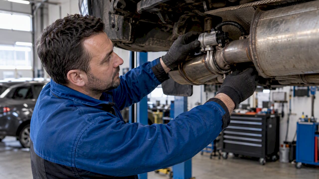
Exhaust flap control depends on the purpose of the valve, its actuator and the software that commands it. An acoustic valve in a silencer is not interchangeable with an exhaust-pressure valve used for other engine functions. Identify the installed system and diagnose its faults before considering a calibration change.
Exhaust flap control starts with system identification
Record the vehicle and engine, controller hardware and software IDs, valve location and actuator part number. Determine whether the component controls sound routing, exhaust pressure, thermal management or an exhaust-braking function. Similar terminology can describe different hardware and strategies.
Do not assume that the transmission controller operates the flap or that every application uses position feedback. Actuation may be electric or vacuum-operated, and control can involve a dedicated module. The wiring diagram and vehicle-specific service information establish the architecture.
The relevant inputs may include operating mode, load, engine speed or temperature, but there is no universal set of maps or opening thresholds. The guide to ECU identification explains why matching the software version matters before interpreting any calibration.
Separate mechanical, electrical and learning faults
Save the complete diagnostic report, including the reporting module, full DTC, symptom code, status and freeze-frame data where available. Check the linkage and valve for restriction using the manufacturer’s procedure. Inspect the relevant supply, ground, connectors, wiring or vacuum circuit before attributing the complaint to software.
Use supported actuator tests and compare commanded and reported position when those values exist. A reported position is not independent proof that the valve and linkage physically moved as intended. Likewise, a mechanical fault cannot be repaired by hiding its diagnostic code.
Do not apply battery voltage to unidentified actuator pins as a generic bench test. Integrated electronics, communication lines and drive circuits require the correct test method and limits. Some procedures require basic settings or end-stop learning after replacement; others do not. A replacement part alone does not establish that learned values remain valid.
Read diagnostic examples within their application
Die DEUTZ EMR L1 diagnostic list, identified as software version 24.15.04, distinguishes calibration, learning, communication, position and control-deviation faults. In that document P154B-00 denotes unavailable sensor-position data. It should not be relabeled as a universal control-circuit code or applied to an unrelated passenger car.
Die Bentley exhaust-flap bulletin 2069484/2 concerns specified Continental GT/C and Flying Spur V8 applications and matching symptom codes. It calls for checking campaign applicability and, where appropriate, wiring integrity. For that particular repair verification, it specifies retesting in Sport mode rather than a road test.
These examples show why neither a universal DTC interpretation nor a mandatory full drive cycle is a sound substitute for the applicable service procedure.
Define the requested behavior before editing
Distinguish restoring factory operation after a repair from intentionally changing flap behavior. Repair may involve a correct replacement part, coding, a software update or a learning routine without any custom file edit. A noise complaint also needs diagnosis before a permanent position command is considered.
For a supported calibration change, document the intended operating conditions and the maps or parameters involved. Confirm definitions against the exact software build, preserve unrelated functions and identify dependencies on monitoring, thermal strategies or other engine controls.
Record existing settings and retain the original read where the tool supports it. Document read coverage: a calibration-only or virtual read is not automatically a complete recovery backup. Verify the tool, protocol, file format and required validation before writing. Checksum handling must be assigned explicitly; it is not proof of correct behavior or guaranteed recovery.
Verify the repair or change against a defined scope
Follow the relevant installation, coding and learning instructions. Confirm that settings or software were applied, examine the fault status and repeat the diagnostic tests that established the original complaint. Where position feedback exists, compare it with the command under the operating conditions specified for the test.
Include relevant operating modes and thermal conditions rather than declaring success from one idle observation. However, do not substitute an arbitrary road-test duration for a manufacturer’s specified stationary test. A clean fault scan alone cannot establish correct mechanical operation, noise compliance or emissions performance.
Keep the before-and-after evidence, the software identification and any unresolved symptom. If a discrepancy remains, investigate its cause before further edits. Repeatedly clearing DTCs is not a verification method.
Assess noise and emissions requirements separately
The valve’s actual function and the affected monitoring determine which compliance questions need investigation. Do not classify every exhaust-flap adjustment as an emissions defeat device merely because it changes sound. Equally, sound-oriented wording does not establish that a change has no effect on emissions controls.
Die EPA’s November 2020 tampering policy discusses documented evidence supporting a reasonable basis that a modification does not adversely affect emissions. It is a nonbinding enforcement policy; absence of that documentation is not, by itself, a violation. Its scope also addresses emissions-related onboard diagnostics.
A customer declaration or competition label does not provide blanket approval. Evaluate the applicable emissions and noise requirements for the vehicle, jurisdiction and modification. This U.S. policy is not a worldwide road-use authorization, and a diagnostic scan is not an emissions or noise certification.
Keep the workshop scope separate from the file request
A workshop quotation should distinguish diagnosis, replacement hardware, learning or coding, any supported file modification and verification. None of those stages has a universal completion time. File availability and compatibility must be established for the actual controller rather than inferred from a manufacturer name.
Use the current TuningBot Preisliste for the listed service terms. Do not assume that a file charge includes physical repairs, checksum correction, every additional service or a guaranteed delivery window. This article explains the technical assessment; it does not promise support for every exhaust-flap system.
Häufig gestellte Fragen
Does every exhaust flap use position feedback and end-stop learning?
No. Actuation, feedback and learning requirements depend on the installed system. Confirm them from the applicable wiring and service information.
Can software repair a seized valve or damaged wiring?
No. Diagnose and repair the physical fault. Suppressing a DTC does not restore the component or prove that it operates correctly.
Is a full drive cycle required after every exhaust-flap repair?
No. Verification is application-specific. Some service procedures specify stationary actuator or operating-mode tests instead.
Does a fault-free scan prove that a flap modification is compliant?
No. Diagnostic status alone does not establish mechanical function, emissions compliance or noise compliance.