

 EnglishEN
 ItalianoIT
 DeutschDE
 EspañolES
 FrançaisFR
 РусскийRU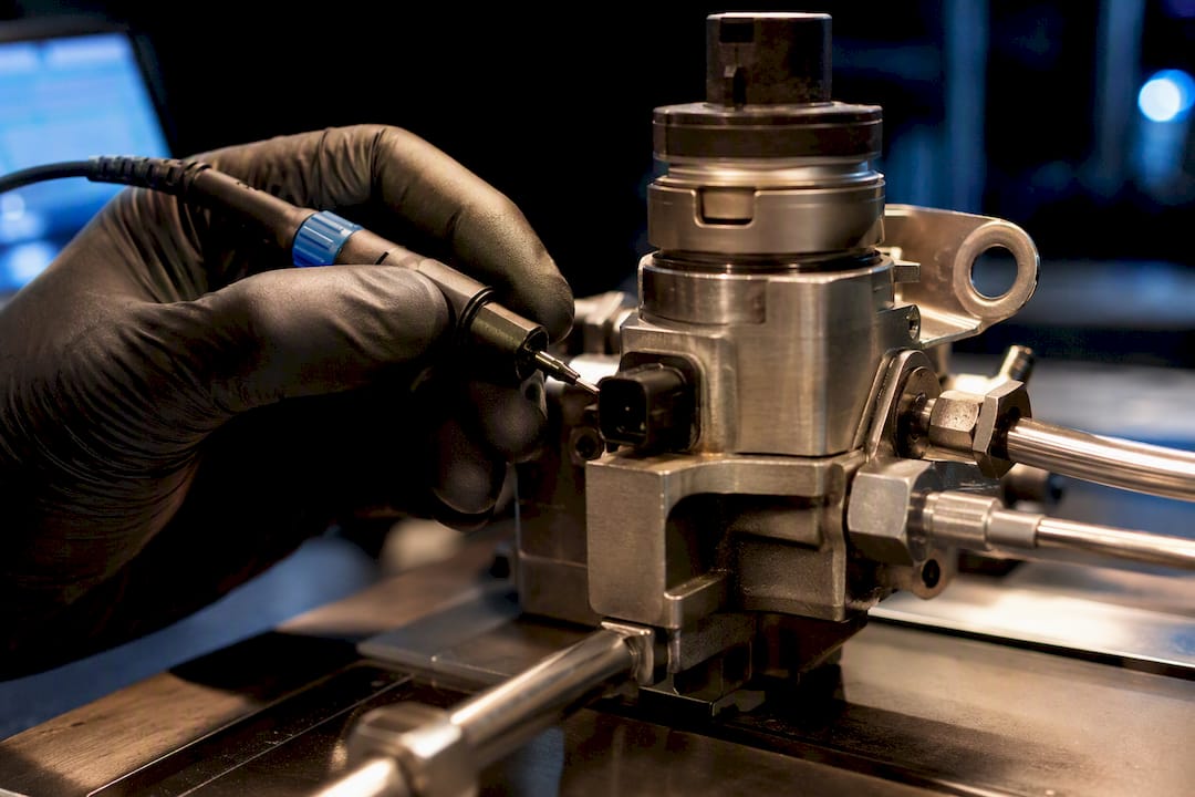
HPFP control tuning concerns how an ECU regulates high-pressure fuel delivery. The first question is which pump and control strategy are installed. A cam-driven gasoline direct-injection pump with timed valve control is not a universal model for every gasoline or diesel system. Diagnosis should connect pressure demand, measured response, electrical command and hardware condition before any calibration change.
HPFP control tuning depends on the pump architecture
Identify the pump part number, ECU software, fuel type and any hardware changes. Some gasoline direct-injection systems control effective pump delivery through the timing of a spill or inlet valve. Diesel common-rail systems may use an inlet metering unit, a rail-pressure control valve, or coordinated control elements.
Bosch’s CP4 documentation, for example, describes metering-unit and electric-suction-valve variants. These should not be treated as the same calibration problem as a particular GDI pump’s base-angle table.
MFV, quantity-control valve and spill valve are not interchangeable labels across all manufacturers. Confirm the function, electrical drive and command convention for the installed component. A map displayed as an angle, a percentage or a modeled quantity needs its own definition.
Check the low-pressure supply under the relevant conditions
Compare feed pressure with the pump and vehicle specification, including the operating conditions that produce the complaint. A satisfactory static reading does not establish sufficient supply during demand. Conversely, a low rail-pressure trace alone does not prove inlet cavitation.
Investigate fuel level and condition, filter restriction, supply-pump operation, wiring, voltage and applicable control commands. Temperature and fuel composition can affect delivery and required fuel quantity. Do not use octane rating as a direct measure of lubricity or assume every pressure disturbance is caused by hot fuel.
Fuel systems can retain hazardous pressure after shutdown. Use the specified depressurization procedure and correctly rated equipment; do not loosen a high-pressure connection to observe flow.
Use logs and electrical measurements for different questions
ECU logging can show target pressure, measured rail pressure, RPM, fuel demand and control output where those channels exist. Confirm whether a value is a command, estimate or measurement. An ECU generally does not expose a directly measured mechanical valve-closing angle simply because it logs a requested angle.
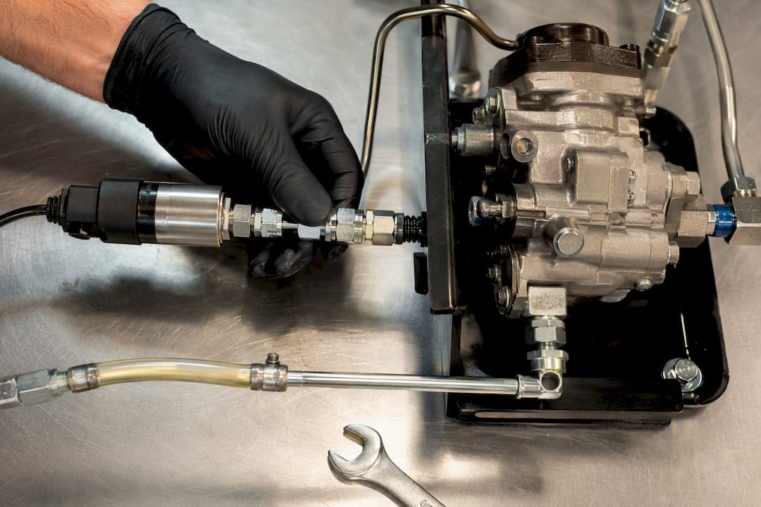
A suitable oscilloscope and current measurement can help investigate electrical drive and timing relative to an appropriate reference. The required bandwidth, sampling rate, probes and connections depend on the signal and driver circuit. There is no universal minimum sample rate that validates every pump.
The start of a current rise is not automatically the instant a valve moves or seats. Mechanical response must be inferred using the applicable component method and corroborating evidence. Do not calculate a new latency table from electrical edges alone and present it as a measured mechanical delay.
Separate the base model, feedback and actuator characterization
A feedforward model estimates the command required for the expected demand; feedback corrects remaining pressure error. The available maps and how they combine are ECU-specific. A stock production strategy should not be redesigned into another controller’s “percent volume” method merely because it works in a development project.
Before changing feedback gains, check the hardware characterization, demand model and operating limits. If an upgraded pump manufacturer supplies validated calibration data for the exact application, use that information as the starting reference.
Do not zero the holding-current phase as a generic setup step. Pull-in current, holding current, duty and actuation timing affect valve operation and must follow the driver and pump specifications. Neither a universal angle range nor a P-then-I sequence applies to every HPFP controller.
Interpret pressure errors without assigning a single cause
| Observation | What to distinguish |
|---|---|
| Target exceeds actual pressure under demand | Supply restriction, pump capacity, leakage, sensor error, command limit or incorrect calibration. |
| Pressure oscillation | Demand changes, electrical or hydraulic behavior, control interaction and measurement artifacts. |
| Control output stays at a limit | An infeasible demand, an actuator fault, an incorrect model or insufficient control authority. |
| Pressure reaches a plateau | Capacity limit, relief behavior, commanded limit or sensor range; the graph alone cannot identify which. |
Relief arrangements and maximum operating pressures vary. Do not assume every pump has the same internal bypass or that repeated pressure loss proves spring fatigue. Pressure relief is a protective function, not a calibration target.
Validate the change against the complete fuel system
A higher-capacity pump does not automatically increase the permitted rail pressure. Pump, rail, lines, injectors, seals, sensors and ECU strategy must be compatible with the intended operation. Some upgrades require revised characterization; others have different documented requirements.
Review pressure tracking alongside the relevant fueling and combustion channels. Stage testing from basic operation to the intended load range in a controlled environment, with defined abort conditions. Retain pressure plausibility and other protective responses.
Keep matched files and logs, fuel details, hardware part numbers and test conditions. If a result deteriorates, return to a documented baseline and investigate. A file review cannot verify an unmeasured supply fault or certify the physical condition of a pump.
Perguntas frequentes
Does every upgraded HPFP require the same tuning changes?
No. Requirements depend on pump construction, ECU strategy and the upgrade supplier’s data. Do not assume a universal scaling or pressure increase.
Is low rail pressure proof that the HPFP is failing?
No. Supply restriction, leakage, sensor errors, electrical faults, control limits and calibration can produce similar symptoms.
Is the low-pressure fuel-pump module the same as HPFP control?
No. A separate module may control the tank or supply pump, while high-pressure regulation follows another strategy. Identify the component before selecting a programming procedure.
Can a scope directly measure metering-valve mechanical latency?
An electrical trace alone does not establish mechanical closing time. Use the component-specific measurement method and corroborating pressure or position evidence.
References and further reading
- RA338 and RA405 HPFP tuning guide — Pump-specific supplier guidance, not a universal HPFP calibration method.
- rusEFI: HPFP control strategy discussion — Development discussion for its own implementation.
- US9458806B2: spill-valve timing correction — A described invention, not a service instruction for every pump.