

 EnglishEN
 ItalianoIT
 DeutschDE
 PortuguêsPT
 FrançaisFR
 РусскийRU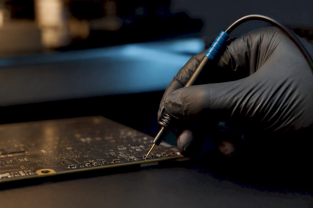
AutoTuner boot mode guide workflows should begin with exact ECU identification and AutoTuner’s current protocol instructions for that specific control unit. Boot is a low-level access method used on supported ECUs when the protocol requires PCB-level access; it is not automatically a last resort, does not universally bypass OEM security, and does not guarantee that a later OBD workflow will become available. Connection points, power requirements, memory access, integrity handling and recovery behavior are all ECU- and protocol-specific.
TL;DR:
- Use Boot only where AutoTuner lists and documents it for the exact ECU/TCU.
- Do not treat Boot as universally safer, more complete or more invasive than every other access mode; the practical risk depends on the ECU and procedure.
- Do not use a fixed 13.5–14.4 V rule for every ECU; follow AutoTuner’s exact power specification.
- Do not assume checksum mismatch proves poor probe contact or that every write requires byte-for-byte readback.
- If a read/write fails, stop repeated blind attempts and follow the documented recovery path for that protocol.
AutoTuner Boot Mode Guide: When Boot Access Is Appropriate
An AutoTuner boot mode guide should explain that OBD, Bench and Boot are separate access methods. Which one is appropriate depends on AutoTuner’s protocol support, ECU state and the operation required; Boot should not be described as universally last-resort.
Typical Boot use cases include protocols that explicitly require Boot, low-level recovery on supported ECUs, or access to memory regions unavailable through other supported methods.
- OEM security locks that block OBD or bench access entirely, common on newer Bosch and Continental units with tightened cryptographic protection.
- Corrupted or dead firmware, where the ECU no longer responds on OBD or bench because the calibration itself is damaged, not the hardware.
- Failed OBD access after a bad flash, where a previous attempt left the unit unresponsive and boot is the only way back in.
Some supported ECU workflows may include vendor-specific unlock or patch procedures, but the result and future access method are ECU-specific. Do not assume one Boot session permanently unlocks every ECU for OBD.
AutoTuner Boot Mode Guide: Required Hardware
Required hardware varies by ECU. Confirm the exact probe, cable, adapter and power instructions before opening or connecting the unit.
Use only the hardware listed by AutoTuner for the exact ECU/protocol.
- AutoTuner tool with current software/firmware and an active protocol for the exact ECU.
- The exact probe, cable, adapter or universal-box combination specified by AutoTuner for that ECU.
- A regulated power source meeting the protocol’s voltage/current requirements.
- ESD-safe work area and appropriate mechanical tools if the ECU must be opened.
- The official AutoTuner connection diagram and pin/test-point reference for the exact control unit.
Workshop supplies that round out a proper boot station include a microscope or magnifier for pad inspection, a temperature-controlled soldering station, an anti-static mat and wrist strap, connector clamps sized for the ECU family you service most, and labeled cable harnesses so you’re not improvising connections mid-session.
Hardware requirements are ECU-specific. Use the current protocol page rather than generalizing from Bosch or non-Bosch families.
Consejo profesional: Before you order parts, pull the ECU’s part number and check it against compatibility lists. Ordering the wrong probe for a unit is a common reason first-time boot sessions stall before they start.
AutoTuner Boot Mode Guide: Protocol-Specific Read/Write Workflow
Boot work should follow AutoTuner’s exact protocol sequence. There is no universal step order that safely applies to every ECU.
- Identify the exact ECU hardware/software and open the matching AutoTuner protocol instructions.
- Confirm the supported Boot hardware, connection points and power requirements before disassembly.
- Preserve photos/notes of connectors and board access where useful for reassembly and support.
- Connect only as shown in the protocol diagram; do not substitute probe or pinout assumptions from a related ECU.
- Perform the read/ID operation supported by that protocol and preserve the original source package unchanged.
- Edit or process only the file/memory region expected by the documented write workflow.
- Use checksum/signature/integrity handling as required by the exact ECU/editor/flasher workflow.
- Write using AutoTuner’s documented procedure and stop if the tool reports an integrity, communication or recovery error.
- After completion, confirm ECU communication, identification and DTC state before vehicle-side validation.
Boot can require direct board access, but physical invasiveness and risk depend on the ECU construction and connection method. Follow the documented procedure and avoid generalizing one ECU family’s setup to another.
AutoTuner Boot Mode Guide: Probe, Cable and Connection Setup
The physical connection method must match the exact ECU and AutoTuner diagram. Probe, solder, universal cable or box usage should be taken from the protocol documentation, not improvised.
Non-Bosch ECUs don’t have that standardized port, which is where the universal cable and universal box take over. These require wiring per the ECU’s own diagram, connected to the tool’s BOOT connector, and the process demands that you confirm the pinout before applying any power.
A few habits separate a stable connection from an intermittent one:
- Use the exact AutoTuner probe/cable method listed for the control unit.
- Avoid excessive probe force or unnecessary soldering on exposed pads.
- Secure temporary connections so they cannot move during a read/write.
- Inspect pads and connectors before applying power.
- Do not reuse a connection diagram from a similar-looking ECU unless AutoTuner explicitly documents compatibility.
Consejo profesional: If a pad looks worn or oxidized under magnification, clean it with isopropyl alcohol before soldering. A probe that “seems” connected but sits on a thin oxide layer will pass a resistance check and still drop the connection under load.
AutoTuner Boot Mode Guide: Power and Connection Safety
Power and grounding are critical, but voltage/current requirements are ECU- and protocol-specific. Use AutoTuner’s documented power instructions for the exact unit.

Use a regulated supply appropriate to the ECU and follow the voltage/current guidance in the AutoTuner protocol. Do not apply one universal 13.5–14.4 V value to all ECUs.
Non-negotiable rules for every session:
- Follow AutoTuner’s voltage/current and power-sequencing instructions for the exact ECU.
- Confirm polarity and ground connections before power is applied.
- Use ESD precautions while the ECU is open.
- Avoid USB or improvised supplies unless the protocol explicitly specifies them.
- Stop immediately if the supply current, connection or tool behavior differs from the documented procedure.
A short circuit introduced during a boot session doesn’t always show up immediately. Sometimes the ECU appears to read and write normally, then fails intermittently once it’s back in the vehicle, which is exactly why power and ground checks come before any connection, every time.
AutoTuner Boot Mode Guide: Troubleshooting Failed Reads and Writes
Failed reads/writes can result from connection, power, pinout, ECU state, protocol mismatch, software/firmware, file or integrity issues. Diagnose from the AutoTuner log and protocol documentation.
A checksum or integrity error does not identify one specific hardware cause. Check the file type, integrity workflow, protocol, connection and tool log before attempting another write.
Do not use a generic recovery checklist across all ECUs. Follow the exact AutoTuner recovery instructions for the protocol and stop if the documented path is unclear.
- Check the exact ECU/protocol selection and AutoTuner connection diagram.
- Review tool logs for communication, voltage, access or integrity errors.
- Re-check power, ground and physical connection only against the official procedure.
- Do not change pad, pinout, voltage or recovery method by trial and error.
- If the ECU becomes unresponsive, use only the documented recovery path or escalate to AutoTuner support.
| Síntoma | What to verify first |
|---|---|
| Read does not start | Exact protocol, connection diagram, power state and tool log. |
| Integrity/checksum error | Correct file type, editor/flasher integrity workflow and protocol. |
| ECU unresponsive after write | Stop further blind writes and use the documented recovery/support path. |
| Intermittent communication | Connection stability, power/ground and cable/probe setup per vendor instructions. |
Before reinstalling, confirm the tool reports a successful operation, ECU identification is correct, communication is restored and DTC state is understood. Additional readback checks are protocol-specific.
AutoTuner Boot Mode Guide: Confirming ECU Support
Confirm support using AutoTuner’s current compatible-vehicles database and the exact ECU’s Boot/help article. If the control unit or procedure is not documented, do not infer support from a related family.
If an ECU is not listed or the Boot procedure is not documented, do not infer compatibility from a related family or improvise a pinout. Escalate to AutoTuner support or use another documented method.
For units that genuinely fall outside documented support, and for cases where the risk of a failed attempt outweighs the value of doing it in-house, deferring to advanced engineering support or a dedicated file service is the more defensible call than improvising a connection on an ECU you can’t verify.
AutoTuner Boot Mode Guide: Software and Connection Checklist
Keep AutoTuner software, drivers and tool firmware current according to the vendor’s requirements. Connection troubleshooting should follow AutoTuner support guidance.
Run through this before every boot session, not just the first one:
- Confirm the AutoTuner software version matches the tool’s firmware version, since mismatches are a frequent cause of a tool that connects but won’t recognize BOOT mode.
- Check that the software shows the BOOT connector as online before you attach anything to the ECU.
- If the tool isn’t recognized, reinstall the driver rather than troubleshooting further downstream.
- Try an alternate USB port, ideally a direct motherboard port rather than a hub, if the connection drops intermittently.
A software-visible Boot connection does not prove the ECU-side hardware setup is correct. Use the tool log and vendor procedure rather than assuming the fault is hardware or software.
AutoTuner Boot Mode Guide: When to Escalate
A file service is useful when the workshop has a valid supported Boot read but does not want to perform the calibration itself.
For related technical context, use the verified AutoTuner Tool Guide, ECU File Writing Guide y Checksum Correction Guide.
Before ordering, check Cobertura del servicio ECU y las Lista de Precios Pública.
The workshop remains responsible for obtaining the Boot read correctly and for the final programming/recovery procedure.
AutoTuner Boot Mode Guide: Workshop Priorities
The most useful habits are exact ECU identification, protocol documentation, connection photos where relevant, and recording tool/software versions for traceability.
Record the AutoTuner software/firmware version and exact ECU ID with the job so any later recovery or support case has the required context.
If a read/write result is unclear, stop and escalate rather than guessing at a patch, checksum or recovery method.
How TuningBot Fits Into AutoTuner Boot Workflows
TuningBot can process supported AutoTuner Boot-origin source files once the exact ECU and read workflow are confirmed.
Submit a supported source file through Reprograma tu archivo after confirming the ECU and requested service.
This article stays technical and informational so commercial ECU-file/service keywords remain concentrated on TuningBot’s service and order pages.
Sources and Further Reading
- AutoTuner — Boot flash method — official AutoTuner Boot reference.
- AutoTuner — Bosch Probe ATP050 — official AutoTuner probe reference.
- AutoTuner — Universal Cable + Universal Box — official AutoTuner universal connection reference.
- AutoTuner — Boot procedure — official procedure reference.
- TuningBot — AutoTuner Tool Guide — verified internal AutoTuner reference.
- TuningBot — ECU File Writing Guide — verified internal programming reference.
- TuningBot — ECU File Checksum Correction — verified internal integrity reference.
PREGUNTAS FRECUENTES
How Do I Switch to Boot Mode?
Select Boot only when AutoTuner documents Boot support for the exact ECU, then follow that protocol’s connection and power instructions. Do not use a generic pin/probe sequence.
Does AutoTuner Boot Mode Clone the ECU?
Boot mode provides the memory access defined by the protocol. Whether the returned data is sufficient for cloning depends on the ECU, memory regions, immobilizer/security data and supported workflow.
How Do You Unlock a Locked ECU?
Unlock behavior is ECU- and vendor-specific. Some supported protocols include an unlock/patch procedure, but there is no universal Boot patch that permanently unlocks every ECU.
What Is Boot Mode in ECU Tuning?
Boot is a low-level read/write access method that may require direct PCB/test-point interaction on supported ECUs. Exact memory access and procedure depend on the protocol.
What Hardware Do I Need for a Boot-Mode Session?
Use only the AutoTuner probe, cable, adapter, universal box and power setup specified for the exact ECU/protocol.