

 ItalianoIT
 DeutschDE
 EspañolES
 PortuguêsPT
 FrançaisFR
 РусскийRU
Start of injection tuning guide workflows should begin with exact ECU, injector system and combustion-strategy identification. An SOI table is not always one simple RPM-versus-load map, and final injection timing may be shaped by torque/load request, rail pressure, pilot/main/post injection scheduling, temperature, emissions and protection strategies. There is no universal 10–15° BTDC target or 1–2° step size that applies across modern diesel ECUs; changes should come from the actual platform, verified definitions and measured combustion response.
TL;DR:
- SOI strategy is ECU-specific; modern diesels may use multiple injection-event and correction strategies.
- Do not use a universal 10–15° BTDC target or fixed 1–2° tuning step.
- Pilot, main and post injection events should be coordinated only where the platform uses them in that operating region.
- Cylinder-pressure/ROHR analysis is the strongest direct validation method where available; proxies are less direct.
- Checksum/signature handling is file- and tool-specific.
Start of Injection Tuning Guide: What an SOI Map Represents
SOI is not a single number. Depending on the ECU, timing may be indexed by RPM, injected quantity, torque/load, rail pressure or other state variables, with interpolation and corrections applied across the operating range.
Injection and ignition delay depend on rail pressure, injector characteristics, temperature, mixture formation and combustion conditions. Higher RPM often changes the crank-angle timing required for similar combustion phasing, but the relationship is not fixed across every engine.
Do not expect every diesel SOI surface to rise uniformly with RPM/load. Shape and direction depend on ECU strategy, injection event, combustion target and emissions constraints.
- Main injection timing commonly sits around 10 to 15 degrees BTDC at typical cruise conditions, with wider variation at idle and full load.
- Injector latency and ignition delay behave as near-constants for a given hardware setup, which is the entire reason the ECU has to advance timing with speed to hold combustion phasing steady.
- Interpolation between calibrated points means a single cell edit rarely stays isolated. It ripples into neighboring operating points.
Start of Injection Tuning Guide: Inputs and Corrections
A base or main timing table can be only one part of the final command. The ECU may apply event-specific, temperature, pressure, emissions, noise and protection corrections.
- Crank and cam position signals establish engine phase and cylinder synchronization. Without an accurate crank/cam relationship, the ECU cannot know where TDC actually is, and every SOI command becomes meaningless.
- Rail pressure and injector latency shift the effective start point because higher rail pressure changes how fast fuel actually leaves the nozzle once the command fires.
- Coolant and intake air temperature feed cold-start and warm-up corrections, since ignition delay lengthens in cold fuel and cold air.
- Barometric pressure and altitude adjust for reduced air density, which changes ignition delay and combustion speed at elevation.
- EGR flow and air-density estimates factor into the corrections because diluted intake charge burns differently than fresh air, and the base map alone cannot account for that on its own.
Bosch, Denso, Continental and other diesel ECUs use different timing architectures. Do not assume one additive/multiplicative correction structure without confirming the exact software.
Start of Injection Tuning Guide: Map and Event Coordination
A start of injection tuning guide should note that injection timing usually depends on several interacting strategies, but the exact map family differs by ECU and injection system.
- Main injection timing: Primary timing strategy for the main event where exposed.
- Pilot injection timing: Used only where the ECU schedules pilot events in the relevant operating region.
- Post injection timing: May be active for emissions/aftertreatment strategies and should not be confused with main SOI.
- Temperature corrections: Cold-start, warm-up or thermal corrections vary by ECU.
- Rail-pressure/injector model: Pressure and injector behavior can influence commanded/effective timing.
- Cylinder balancing/trim: Where available, per-cylinder corrections may alter event timing or quantity.
- Emissions/protection logic: EGR, soot, noise, NOx and thermal strategies can modify or constrain timing.
Correction behavior can be additive, offset-based, modeled, event-specific or encoded differently depending on the ECU. Confirm the table function before editing it.
Start of Injection Tuning Guide: How Final Timing Is Determined
There is no single calculation sequence shared by every common-rail diesel. The final timing command depends on the ECU’s torque/fuel model, injection-event scheduling and active corrections.
Many systems derive timing from injected quantity or torque/load together with RPM, then apply additional event and operating-condition logic. Treat that as a common pattern, not a universal formula.
SOI calibration balances torque, efficiency, noise, emissions, cylinder pressure and exhaust temperature. The direction and magnitude of each trade-off are engine- and operating-point-specific.
- Torque and power generally favor slightly earlier SOI in the mid-load range, since more of the combustion event occurs closer to peak cylinder volume efficiency.
- NOx formation rises with advanced timing because earlier combustion produces higher peak flame temperatures, the primary driver of NOx chemistry.
- Soot and smoke tend to rise when timing is retarded too far, since combustion runs later into the expansion stroke and burns less completely.
- Mechanical stress climbs sharply with excessive advance. Advancing injection timing too far raises peak cylinder pressure and combustion pressure rise rate, which is the direct mechanical link between an aggressive SOI edit and a knocking, stressed engine.
Choosing guardrails means picking a target zone, not a single number: how much NOx increase is tolerable against a smoke limit, how much peak pressure rise the block, head gasket, and rod bearings can absorb over the long run, and how the pilot injection is coordinated to blunt the noise and pressure spike that comes with any main-event advance. A calibration that ignores that last piece often looks fine on a torque curve and fails quietly on durability months later.
Start of Injection Tuning Guide: How to Approach Timing Changes
Crank degrees are the usual physical reference for SOI, but some calibration formats use encoded values or normalized scales. Convert only when the ECU definition and conversion are known.
A professional SOI workflow should be evidence-driven rather than based on one universal degree increment or RPM region.
- Identify the exact SOI table/event and its physical units from verified definitions.
- Establish a matched baseline at the operating points you intend to change.
- Make the smallest justified change that your measurement capability can resolve; do not default to 1–2 degrees.
- Change one operating region or strategy at a time where practical.
- Coordinate pilot/post events only where the ECU strategy and logs show they must move with the main event.
- Validate combustion, torque, EGT and emissions-related response before the next revision.
This staged, degree-based approach lines up with the rail pressure, SOI, and smoke limit triad that experienced Stage 1 tuners treat as the foundation of a sensible calibration. None of those three variables should move in isolation from the other two.
Pro Tip: Log the exact same RPM and load point before and after every SOI edit, not a rough average across a pull. A half-second timing shift buried inside a wide load window will hide the very deviation you are trying to catch.
Start of Injection Tuning Guide: Validation
Editing the table is only part of the job; validation must confirm the intended combustion, torque and thermal result without creating new faults.
Cylinder-pressure measurement and rate-of-heat-release analysis are the most direct ways to evaluate combustion phasing where that instrumentation is available.
Shops without pressure transducers can lean on a set of practical proxies:
- Cylinder pressure/ROHR where instrumentation is available.
- EGT and exhaust-temperature trends at matched operating points.
- Lambda/smoke or combustion-quality indicators where relevant.
- Rail pressure, injection quantity/duration and engine speed.
- Torque or BSFC on a repeatable dyno/test method where output or efficiency is the objective.
- DTCs, noise/knock/vibration data and cylinder-balance indicators where available.
There is no universal one-degree step or fixed test-point recipe. Use repeatable matched conditions and pre-defined stop criteria based on the engine and available measurements.
Watch for these red flags on every verification pass:
- Cylinder-to-cylinder variance widening after the change, a sign of uneven trim response.
- Peak pressure (Pmax) occurring earlier in the cycle than your baseline, a classic sign of over-advance.
- Audible knock or a spike in structure-borne noise on a knock sensor trace.
- Sudden EGT climbs that were not present at the same load point before the edit.
- Injector deviation or timing correction fault codes appearing after the flash.
Start of Injection Tuning Guide: Advance vs Retard Effects
Every SOI change is a trade, never a free gain, and the direction you move determines which side of that trade you land on.
- Advancing timing generally raises torque and can improve brake specific fuel consumption (BSFC) up to a point, because more of the combustion energy is captured while the piston still has useful leverage on the crank.
- Advancing too far drives NOx up sharply, since earlier combustion means higher peak flame temperature, and it raises peak cylinder pressure and pressure rise rate to levels that risk knock and mechanical stress.
- Retarding timing typically reduces peak pressure and can lower NOx, which is part of why factory calibrations lean conservative at part load.
- Retarding too far pushes combustion later into the expansion stroke, increasing soot and unburned hydrocarbons while efficiency drops.
There is no universal “correct” SOI value that satisfies power, emissions, and durability simultaneously. Every calibration decision is a negotiated position between those three, backed by measurement rather than a spec sheet guess.
Start of Injection Tuning Guide: Guardrails and Stop Criteria
SOI changes require mechanical and thermal guardrails, but the allowable limits and increment size must come from platform data rather than generic rules.
- Define mechanical and combustion-pressure limits from engine/platform data where available.
- Define thermal limits from EGT, coolant, oil and aftertreatment constraints relevant to the application.
- Use repeatable matched test conditions and revert when a new fault, abnormal noise, pressure/temperature deviation or drivability issue appears.
- Do not infer cylinder-to-cylinder combustion balance from timing tables alone.
- Keep a known-good source/release revision and a tool-supported recovery path.
Pro Tip: Treat a fault code or knock event as a stop sign, not a puzzle to solve with another timing tweak. Revert to the last verified baseline first, then diagnose from a known-good starting point.
Start of Injection Tuning Guide: Tools and Workflow
A safe SOI workflow depends on three categories of tools working together: a map editor capable of reading and writing the specific ECU’s calibration structure, a flasher tool to write the corrected file back to the vehicle, and logging hardware to capture the verification data described earlier.
- Calibration software with verified definitions for the exact ECU and injection-event strategy.
- A flashing tool that supports the exact ECU protocol and source-file type.
- Logging/diagnostic tools for rail pressure, injection events, temperatures, torque/load and DTCs.
- Dyno or another repeatable load-control method where torque/efficiency comparison is required.
- Cylinder-pressure instrumentation only where direct combustion-phasing measurement is required.
- The checksum/signature/integrity workflow required by the ECU and flashing tool.
Before any flash: back up the original file, confirm checksum integrity on the edited file, stage the flash rather than pushing every table change at once, and follow a consistent logging protocol so results are comparable run to run. Firmware quirks vary by ECU generation, and a table that behaves as additive on one software version can behave differently on a revision two years later, so never assume identical behavior across firmware without confirming it. Shops looking for a structured software-based verification approach can also reference this technician’s guide to fault detection through diagnostic software for a broader workflow on catching issues before they become drivability complaints.
How TuningBot Supports SOI Calibration Workflows
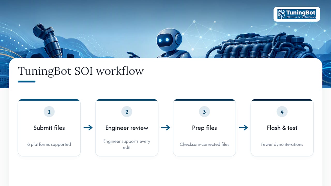
TuningBot can provide calibration files for supported ECU workflows where SOI or related injection-event strategies are available in the exact software.
Before ordering, check ECU Service Coverage, review the public Price List and browse ECU services.
For related technical context, use the verified Fuel Map Tuning Guide, Checksum Correction Guide and ECU Remapping for Professionals.
Submit a supported source file through Tune Your File after confirming the ECU and requested calibration scope.
This article stays technical so commercial diesel/ECU-tuning keywords remain concentrated on TuningBot’s service and order pages.
Our Take: Measure Before You Trust the Table
The biggest mistake we see in SOI tuning is treating the map like a power dial instead of a phasing target. A 2-degree advance that looks identical on paper can behave completely differently depending on rail pressure, pilot coordination, and ambient conditions, which is exactly why rate-of-heat-release analysis.13) exists as a discipline. Shops without a pressure rig on the bench are not out of options. They just need to be more conservative with step size and more disciplined about logging every variable. When measurement capacity is thin, lean on a professionally reviewed file rather than guessing your way to a durability problem.
— TuningBot Technical Team
Using This Start of Injection Tuning Guide in a Workshop
Use this guide to identify the actual injection-event strategy, measurement capability and stop criteria before changing SOI.
If calibration is outsourced, verify the exact ECU in ECU Service Coverage and submit the supported source file through Tune Your File.
The workshop remains responsible for engine condition, programming, legal/emissions use and final validation.
Sources and Further Reading
- HP Academy — Diesel Injection Timing — external educational reference retained unchanged.
- MDPI — Advanced Fuel Injection Timing Study — external research reference retained unchanged.
- The Diesel Store — Fuel Injection Timing Guide — external diesel reference retained unchanged.
- App-Shifter — Diagnostic Software Guide — external diagnostic-workflow reference retained unchanged.
- TuningBot — Fuel Map Tuning Guide — verified internal fueling reference.
- TuningBot — ECU File Checksum Correction — verified internal integrity reference.
- TuningBot — ECU Remapping for Professionals — verified internal professional-workflow reference.
FAQ
What Does an ECU Map Do?
An ECU map is one calibration element used by the controller to determine a command from operating conditions. SOI may depend on multiple maps, models and correction strategies rather than one table alone.
What Are the Symptoms of Incorrect Injection Timing?
Incorrect injection timing can contribute to abnormal noise, smoke, EGT, efficiency, torque, emissions or fault codes, but those symptoms are not unique to SOI errors.
How Do I Start a Fuel-Injected Diesel Engine Safely After a Timing Change?
After programming, confirm communication and DTC state, start at low load and monitor the relevant engine/combustion indicators before progressing to higher-load validation.
What Should My Fuel Injection Timing Be?
There is no universal number. The correct timing depends on engine design, injection system, RPM/load, rail pressure, temperature, combustion target and emissions constraints.
Can TuningBot Help With Custom SOI Calibration Requests?
TuningBot can process supported ECU files where SOI-related calibration is available. Exact service scope depends on ECU ID, source-file type and requested objective.